Separating Relief, Check and Lowering-Valve Faults
- Distinguish pressure protection, backflow prevention and commanded release.
- Match valve symptoms to seat, seal and poppet faults.
- Diagnose safely without using relief adjustment as a shortcut.
- Mechanical body supports — Secure the dump body against unintended movement using supports approved for the equipment before entering a crush zone.
- Hydraulic pressure gauge and compatible test fittings — Observe pressure behavior at the designated test point using equipment rated for the system.
- Digital multimeter — Check whether the lowering-valve coil receives the commanded electrical supply.
- Wrenches — Remove and install accessible valve components after hydraulic lines are depressurized.
- Inspection light and magnifier — Inspect accessible seats, seals, poppets and stems for debris or damage.
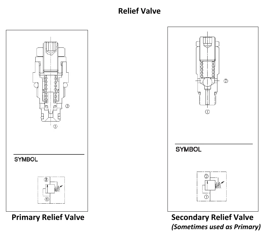
Relief valves protect the hydraulic system against excessive pressure. The documented double-acting arrangement also uses a second relief after the check valve to address cylinder overpressurization associated with thermal expansion.
Debris on a relief-valve seat can prevent the system from reaching maximum pressure. Torn or extruded seals are another listed fault. Driving an adjustment screw fully inward can compress the spring enough to cause early opening or prevent restoration of the specified setting; adjustment is not a substitute for diagnosis.
A check valve uses a lighter spring than a relief valve and permits forward flow with little pressure loss while preventing flow back toward the pump. Its listed problems include debris on the seat, damaged seals and silting that restricts poppet movement.
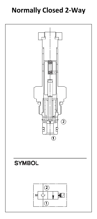
The normally closed two-way valve functions as a solenoid-operated check valve. Coil activation retracts the pilot pin, allows pressure to equalize across the poppet and then permits the poppet to retract. Debris, torn nose seals, silting and a bent coil stem can interfere with operation.
How It Works
Relief valves protect pressure, not load position
A relief valve limits excessive hydraulic pressure; in the documented double-acting arrangement, an additional relief after the check valve protects against cylinder overpressurization associated with thermal expansion. Trapped fluid can increase in pressure as it warms, so protection must address the isolated cylinder side as well as pump delivery. Seat debris or torn or extruded seals can prevent maximum pressure, while forcing the adjustment screw inward can cause early opening or prevent restoration of the specified setting.
Check valves prevent reverse flow
A check valve uses a lighter spring than a relief valve, allowing forward flow with little pressure loss while blocking flow back toward the pump. Debris or damaged seals can compromise closure, while silting can restrict poppet movement. A pressure complaint and a holding complaint therefore require different diagnostic reasoning rather than the same adjustment.
Lowering depends on a pilot-operated opening sequence
The normally closed lowering valve functions as a solenoid-operated check valve: coil activation retracts the pilot pin, pressure equalizes across the poppet and the poppet can then retract. Electrical activation alone does not establish that the hydraulic opening sequence has completed. Debris, torn nose seals, silting or a bent coil stem can interfere with operation.
Step-by-Step Procedure
0/5 doneFigures
Diagnostic Chart
| Symptom | Check | Spec / Expected | Likely cause & fix |
|---|---|---|---|
| The system cannot reach maximum pressure. | Classify the suspected component as a pressure-protection valve. After securing the body and depressurizing hydraulic lines, inspect the relief seat for debris and its seals for tearing or extrusion; investigate previous adjustment rather than turning the screw inward. | No pressure setting is supplied in this lesson. Do not force the relief adjustment screw inward to overcome the complaint. | Seat contamination, damaged seals or an overdriven adjustment screw can interfere with proper relief operation. Basis: Hydraulics-Troubleshooting-Manual 2019 |
| Suspected backflow toward the pump or restricted flow through the check valve. | After depressurization, inspect the check-valve seat and seals, and check for silting that restricts poppet travel. Treat suspected backflow as a diagnostic lead, not proof that the check valve is the only possible leakage path. | The check valve permits forward flow with little pressure loss and prevents flow back toward the pump. | Seat debris or damaged seals can compromise closure; silting can interfere with poppet movement. Basis: Hydraulics-Troubleshooting-Manual 2019 |
| The lowering valve does not release despite confirmed coil activation. | After securing the body and depressurizing hydraulic lines, inspect the pilot-operated opening components for debris, torn nose seals, silting and a bent coil stem. | Coil activation retracts the pilot pin, permits pressure equalization across the poppet and then permits poppet retraction. | Mechanical damage or contamination can interrupt the opening sequence even when electrical activation is present. Basis: Hydraulics-Troubleshooting-Manual 2019 |
| The lowering valve gives no apparent response to the command. | With the body safely secured, use the wiring information and a multimeter to verify supply and return at the coil during the command. Do not loosen hydraulic fittings to test whether the coil is energized. | Use the equipment manufacturer's electrical requirements; no electrical acceptance value is supplied here. | A supply, wiring, connector or return-path fault can prevent coil energization and mimic a hydraulic valve fault. Basis: General shop practice |
At the Bay: Diagnose the Case
CASE 1 / 4
The system cannot reach maximum pressure.
- Test
- Compare
- Correct
Select the next check
Basis: Hydraulics-Troubleshooting-Manual 2019. A likely cause is a hypothesis; confirm it with the applicable service procedure before repair.
Common Bay Mistakes
- ✕ Never rely on hydraulic holding alone while working beneath a raised body.
- ✕ Do not force a relief adjustment screw inward to chase pressure.
- ✕ Do not mistake an energized coil for a successfully opened poppet.
- ✕ Depressurize hydraulic lines before valve service; pump shutdown is not proof of depressurization.
Quick Check
Practice only — not scored.
Plan the Service Sequence
Planning practice only. Follow the applicable manufacturer's instructions, employer safety program and qualified supervision on real equipment.
Plan the first action. Compare the service steps with the bay mistakes.
Hands-on: Shop Test Equipment
Hydraulic Pressure & Relief Gauge
0–5,000 psi gauge on the pump pressure port, DC clamp meter, battery voltmeter
🛠 Equip your bay for this test →Symptom: Routine check before a customer pickup.
Spec limits used
- 3,200 psi — Primary relief (factory preset) (KTI Hydraulics Troubleshooting Manual 2019)
- 1,500 psi — Secondary relief, circuit 111 (KTI Hydraulics Troubleshooting Manual 2019)
- below 9 V — Low-voltage alarm (KTI remote)
- illustrative only — Motor current & voltage drop (General shop practice)
Simulated readings for practice. Always follow the manufacturer's procedure and values on a real trailer.
Source: Hydraulics-Troubleshooting-Manual 2019 — 14-16