Diagnosing Directional and Load-Holding Valves
- Distinguish failure to shift from excessive internal leakage.
- Perform the documented directional-valve movement check safely.
- Diagnose load-holding complaints using the installed arrangement.
- Torque wrench — Control installation torque using the specification for the identified valve.
- Hand wrenches — Remove and install the valve after the load is safely supported and hydraulic lines are depressurized.
- Multimeter — Check coil supply and circuit condition against the equipment wiring information.
- Breather dipstick — Push the identified nose section during the manual's removed-valve movement check.
- Drain pan — Catch residual fluid during valve removal and keep the work area clean.
A directional valve changes the fluid path when its energized coil shifts the spool. Increasing clearance between the spool and cage can produce excessive internal leakage. The manual associates this wear with progressively longer cycles and eventual inability to lift a load.
Listed causes of directional-valve malfunction include an inactive coil, excessive tightening, damaged seals, debris, rust and a bent stem. KTI specifies a maximum of 18 ft-lb for the directional valve discussed in the manual; values vary by maker, and this is not a universal valve torque.
For a valve that does not shift, the documented inspection begins with checking for a bent stem and removing the valve from the manifold after hydraulic lines have been depressurized. The breather dipstick is used to push the identified nose section and manually shift the valve. Failure to move calls for checking debris or replacing the valve.
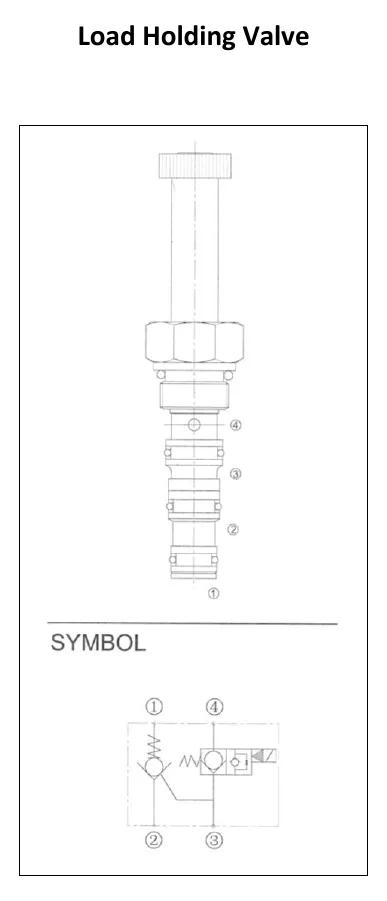
The illustrated load-holding valve checks both cylinder ends. Its coil-operated section permits retraction without the additional restricting orifice described for a dual pilot-operated check arrangement. Debris, a bent stem and air preventing the pilot-operated check from opening are listed faults; this particular arrangement must not be assumed to describe every load-holding valve.
How It Works
Shifting and sealing are different functions
An energized coil shifts the directional-valve spool to change the fluid path, but successful movement does not prove that the valve seals internally. Increasing spool-to-cage clearance lets fluid bypass the intended path; the manual associates this wear with progressively longer cycles and eventual inability to lift a load.
Safe mechanical isolation
Lower the body or secure it with approved mechanical support, isolate unintended operation, and depressurize hydraulic lines before removing a valve; a hydraulic holding valve is not a substitute for mechanical support. For the documented movement check, inspect for a bent stem, remove the valve, and use the breather dipstick at the identified nose section to shift it manually. Excessive tightening is a listed malfunction cause, and the KTI maximum of 18 ft-lb applies only to the directional valve discussed, not to unrelated valves or fittings.
Identify the load-holding arrangement
The illustrated load-holding valve checks both cylinder ends, and its coil-operated section permits retraction without the additional restricting orifice described for a dual pilot-operated check arrangement. Debris, a bent stem, or air preventing pilot opening can interfere with its operation. Confirm the installed arrangement before applying this explanation, because other load-holding designs may operate differently.
Step-by-Step Procedure
0/6 doneKTI directional-valve limit; values vary by maker
| Maximum torque for the directional valve discussed | 18 ft-lb |
Figures
Diagnostic Chart
| Symptom | Check | Spec / Expected | Likely cause & fix |
|---|---|---|---|
| Directional valve does not shift when commanded. | Review coil inactivity, excessive tightening, damaged seals, debris, rust and stem bending; after depressurizing the lines, remove the valve and use the breather dipstick at the identified nose section to check movement. | For the directional valve discussed, maximum torque is 18 ft-lb. If it cannot move manually, check for debris or replace it as directed by the manual. | Inactive coil or mechanical interference from the documented malfunction causes. Basis: Hydraulics-Troubleshooting-Manual 2019 |
| Cycles become progressively longer, followed by inability to lift a load. | Evaluate excessive directional-valve internal leakage rather than treating the complaint solely as failure to shift. | The manual associates this progression with increasing clearance between the spool and cage; no leakage acceptance limit is supplied in the lesson. | Spool-to-cage wear allows excessive internal bypass. Basis: Hydraulics-Troubleshooting-Manual 2019 |
| The documented load-holding arrangement does not permit expected retraction. | Confirm the installed valve matches the illustrated arrangement, then consider check-valve debris, a bent stem and air preventing pilot opening. | The illustrated valve checks both cylinder ends and permits coil-operated retraction without the additional restricting orifice described for a dual pilot-operated check arrangement. | Contamination, stem damage or air interfering with pilot-operated check opening. Basis: Hydraulics-Troubleshooting-Manual 2019 |
| The valve moves manually but does not respond to the electrical command. | With the body safely supported and unintended movement controlled, inspect connectors and wiring, check coil supply during the command, and perform isolated circuit checks using the equipment documentation. | Use the installed equipment's electrical specifications; do not infer coil ratings from valve appearance. | Missing command supply, a poor connection or a coil fault may prevent electrical actuation despite free manual movement. Basis: General shop practice |
At the Bay: Diagnose the Case
CASE 1 / 4
Directional valve does not shift when commanded.
- Test
- Compare
- Correct
Select the next check
Basis: Hydraulics-Troubleshooting-Manual 2019. A likely cause is a hypothesis; confirm it with the applicable service procedure before repair.
Common Bay Mistakes
- ✕ Never remove a valve while hydraulic lines remain pressurized.
- ✕ Do not rely on hydraulic load holding to support an elevated body during service.
- ✕ Do not apply the KTI torque limit to unrelated components.
- ✕ Free manual movement does not prove internal sealing or electrical operation.
Quick Check
Practice only — not scored.
Plan the Service Sequence
Planning practice only. Follow the applicable manufacturer's instructions, employer safety program and qualified supervision on real equipment.
Plan the first action. Compare the service steps with the bay mistakes.
Hands-on: Shop Test Equipment
Hydraulic Pressure & Relief Gauge
0–5,000 psi gauge on the pump pressure port, DC clamp meter, battery voltmeter
🛠 Equip your bay for this test →Symptom: Routine check before a customer pickup.
Spec limits used
- 3,200 psi — Primary relief (factory preset) (KTI Hydraulics Troubleshooting Manual 2019)
- 1,500 psi — Secondary relief, circuit 111 (KTI Hydraulics Troubleshooting Manual 2019)
- below 9 V — Low-voltage alarm (KTI remote)
- illustrative only — Motor current & voltage drop (General shop practice)
Simulated readings for practice. Always follow the manufacturer's procedure and values on a real trailer.
Source: Hydraulics-Troubleshooting-Manual 2019 — 17-19