Tracing Power-Up, Power-Down Operation
- Trace UP commands, extension flow and rod-end return.
- Trace DOWN commands, retraction flow and bore-end return.
- Distinguish primary and secondary relief protection without adjusting valves.
- Digital multimeter — Check motor-start and valve-coil commands against the unit's wiring diagram.
- Hydraulic pressure gauge kit — Observe pressure at manufacturer-approved test points using equipment rated for the unit.
- Flashlight — Locate manifold markings, valve coils and hydraulic connections.
- Inspection mirror — Read obscured port labels and trace connections without reaching beneath an unsupported body.
- Shop wipes — Clean around markings and test connections to improve identification and limit contamination.
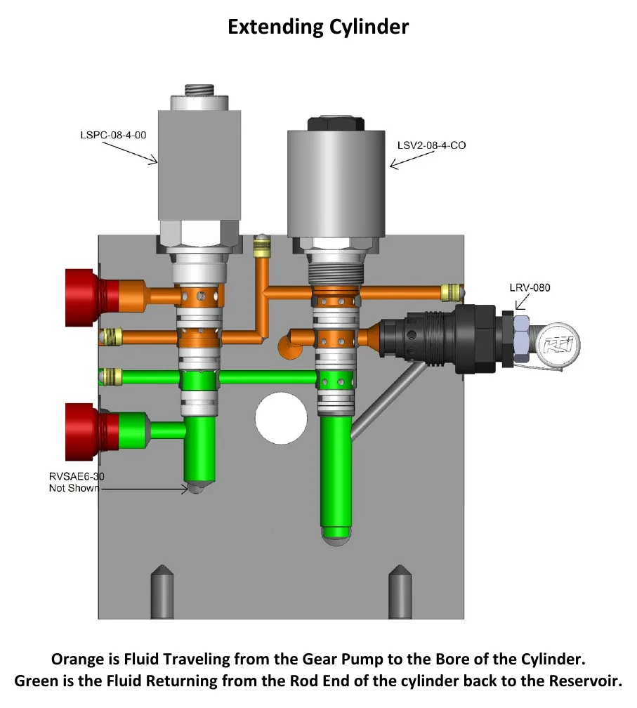
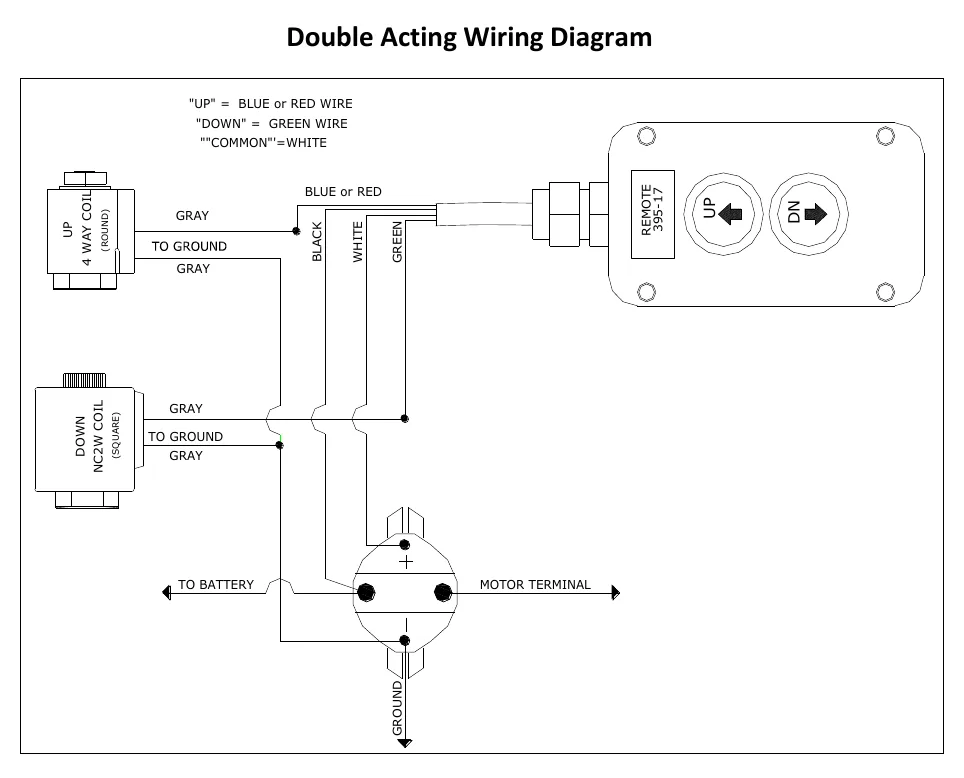
In the documented double-acting arrangement, UP energizes the start solenoid, motor and cylindrical directional-valve coil together. The directional valve shifts, and pump flow passes through the load-holding valve's normally closed two-way section to manifold port A, extending the cylinder.
During extension, pump pressure pilots open another section of the lowering valve so fluid from the cylinder's rod end can return to the reservoir. KTI specifies a 2.5:1 pilot ratio for the illustrated lowering valve; values vary by maker.
DOWN energizes the start solenoid, motor and square lowering-valve coil. Pump flow travels through the directional valve and lower section of the load-holding valve to port B. Energizing the square coil opens the return path for fluid from the cylinder bore.
The circuit has separate relief protection for extension and retraction conditions. KTI specifies a 3,200 psi primary relief and a 1,500 psi secondary relief for the illustrated circuit; values vary by maker. The secondary relief protects against rod-end overpressurization and pressure associated with thermal expansion.
How It Works
UP: powered extension with a piloted return
UP energizes the start solenoid, motor and cylindrical directional-valve coil together; the shifted valve routes pump flow through the load-holding valve's normally closed two-way section to port A, extending the cylinder. Pump pressure also pilots open another section of the lowering valve so rod-end fluid can return to the reservoir; without that escape path, trapped fluid opposes extension. KTI specifies a 2.5:1 pilot ratio for the illustrated lowering valve, but values vary by maker.
DOWN: powered retraction with an electrically opened return
DOWN energizes the start solenoid, motor and square lowering-valve coil, with pump flow passing through the directional valve and lower section of the load-holding valve to port B. The square coil opens the return path from the cylinder bore to the reservoir, allowing the cylinder to retract. A running motor therefore does not prove correct operation: both the pressure supply and the return path must function.
Separate relief functions
The illustrated KTI circuit specifies a 3,200 psi primary relief and a 1,500 psi secondary relief for separate extension and retraction protection. The secondary relief protects against rod-end overpressurization and pressure associated with thermal expansion, because trapped fluid can develop pressure as it warms. These values are not universal, and factory-preset relief valves must not be adjusted without factory consultation.
Step-by-Step Procedure
0/6 doneKTI illustrated double-acting circuit; values vary by maker
| Lowering-valve pilot ratio | 2.5:1 |
| Primary relief setting | 3,200 psi |
| Secondary relief setting | 1,500 psi |
Figures
Diagnostic Chart
| Symptom | Check | Spec / Expected | Likely cause & fix |
|---|---|---|---|
| Motor runs on UP, but the cylinder does not extend. | Verify that UP commands the cylindrical directional-valve coil as well as the motor-start circuit, then trace the documented flow path to port A. | UP energizes the start solenoid, motor and cylindrical directional-valve coil together; extension flow goes to port A. | A missing cylindrical-coil command or failure of the directional valve to shift can prevent the required extension flow. Basis: Hydraulics-Troubleshooting-Manual 2019 |
| Extension stalls despite an apparent pressure supply. | Trace the rod-end return path and verify, using the manufacturer's procedure, that pump pressure can pilot open the lowering-valve return section. | The illustrated KTI lowering-valve pilot ratio is 2.5:1; values vary by maker. | A restricted return path or failure of the piloted section to open can trap rod-end fluid and oppose extension. Basis: Hydraulics-Troubleshooting-Manual 2019 |
| Motor runs on DOWN, but the cylinder does not retract. | Verify the square lowering-valve coil command, trace pump flow to port B and confirm the bore-end return route to the reservoir. | DOWN energizes the start solenoid, motor and square lowering-valve coil; supply goes to port B and bore-end fluid returns to the reservoir. | A missing square-coil command, an unopened bore-end return path or interrupted port B supply can prevent retraction. Basis: Hydraulics-Troubleshooting-Manual 2019 |
| Unexpected rod-end pressure is observed or suspected. | Identify the unit and its applicable relief specifications, then locate the secondary relief function without changing its adjustment. | Illustrated KTI circuit: primary relief 3,200 psi; secondary relief 1,500 psi. Factory-preset relief valves must not be adjusted without factory consultation. | Rod-end overpressurization or thermal expansion of trapped fluid can create pressure that the secondary relief is intended to limit. Basis: Hydraulics-Troubleshooting-Manual 2019 |
At the Bay: Diagnose the Case
CASE 1 / 4
Motor runs on UP, but the cylinder does not extend.
- Test
- Compare
- Correct
Select the next check
Basis: Hydraulics-Troubleshooting-Manual 2019. A likely cause is a hypothesis; confirm it with the applicable service procedure before repair.
Common Bay Mistakes
- ✕ Do not work beneath an unsupported dump body; use manufacturer-approved mechanical support.
- ✕ Do not loosen hydraulic connections to test for pressure; relieve stored pressure before connecting test equipment.
- ✕ Do not assume motor operation proves that the correct valve coil or return path is working.
- ✕ Do not transfer illustrated KTI settings to another unit or adjust factory-preset reliefs without factory consultation.
Quick Check
Practice only — not scored.
Plan the Service Sequence
Planning practice only. Follow the applicable manufacturer's instructions, employer safety program and qualified supervision on real equipment.
Plan the first action. Compare the service steps with the bay mistakes.
Hands-on: Shop Test Equipment
Hydraulic Pressure & Relief Gauge
0–5,000 psi gauge on the pump pressure port, DC clamp meter, battery voltmeter
🛠 Equip your bay for this test →Symptom: Routine check before a customer pickup.
Spec limits used
- 3,200 psi — Primary relief (factory preset) (KTI Hydraulics Troubleshooting Manual 2019)
- 1,500 psi — Secondary relief, circuit 111 (KTI Hydraulics Troubleshooting Manual 2019)
- below 9 V — Low-voltage alarm (KTI remote)
- illustrative only — Motor current & voltage drop (General shop practice)
Simulated readings for practice. Always follow the manufacturer's procedure and values on a real trailer.
Source: Hydraulics-Troubleshooting-Manual 2019 — 9-12