Tracing Power-Up, Gravity-Down Operation
- Trace the UP electrical path and cylinder-extension fluid path.
- Distinguish gravity-down valve operation from powered lowering.
- Locate relief and return-flow paths without altering safety settings.
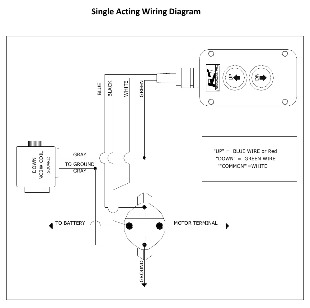
- Digital multimeter — Check command power and ground at the start solenoid, motor, and lowering coil using the supplied wiring diagram.
- DC clamp ammeter — Check whether the motor or lowering coil draws current during its respective command without disconnecting the circuit.
- Flashlight — Locate port P, trace accessible hoses, and inspect wiring and manifold identification.
- Inspection mirror — Read concealed component markings and inspect connections while staying outside the body's movement zone.
- Wheel chocks — Help prevent trailer movement during inspection and controlled operational checks.
In the documented gravity-down arrangement, an UP command supplies battery power to the start solenoid and motor. The energized start solenoid supplies the motor, which drives the gear pump to develop hydraulic pressure.
Pump flow passes through a check valve and leaves the manifold through port P to extend the cylinder. At the end of stroke or maximum load, fluid bypasses to the reservoir through the primary relief valve.
The DOWN command energizes the coil on a normally closed two-way valve. Opening that valve gives cylinder fluid a path back to the reservoir. This lowering sequence differs from a powered-down circuit because the documented DOWN command operates the lowering valve rather than the pump motor.
An optional flow control in the manifold can regulate cylinder retraction speed as fluid returns to the reservoir. Use the supplied single-acting wiring diagram together with the operating sequence to distinguish the motor-start path from the lowering-coil path.
How It Works
UP: electrical power becomes hydraulic flow
The UP command energizes the start solenoid, whose power contacts supply the motor; the motor then drives the gear pump. Pump flow passes through the check valve and exits port P to extend the cylinder, with pressure developing as the load resists movement. Distinguishing the command circuit from the motor power circuit helps explain why a solenoid click alone does not prove that the motor receives usable power.
Relief bypass protects the pressure circuit
At stroke end or maximum load, the documented primary relief valve provides a bypass to the reservoir. Bypass flow limits pressure rather than producing further cylinder extension, and continued operation in bypass converts energy into heat. The factory-preset relief valve is a safety device: do not alter its setting or safety wire.
DOWN: open the return path rather than power the pump
The DOWN command energizes the coil on the normally closed lowering valve, opening a path from the cylinder to the reservoir rather than commanding the pump motor. Gravity supplies the lowering force as fluid leaves the cylinder, while an optional manifold flow control can regulate retraction speed. Use the supplied single-acting wiring diagram to keep the lowering-coil circuit separate from the motor-start circuit.
Step-by-Step Procedure
0/5 doneFigures
Diagnostic Chart
| Symptom | Check | Spec / Expected | Likely cause & fix |
|---|---|---|---|
| UP is selected, but the pump motor does not run. | Trace the UP command through the start-solenoid control circuit and then through the solenoid's motor-supply path using the supplied wiring diagram. | UP energizes the start solenoid, which supplies the motor that drives the gear pump. | An interruption in the command path, solenoid power path, or motor circuit can prevent pump operation. Basis: Hydraulics-Troubleshooting-Manual 2019 |
| The motor runs, but the cylinder does not extend. | Trace the documented flow route through the check valve and port P. Determine whether the cylinder is already at stroke end or the system has reached maximum load before treating bypass as a fault. | Pump flow passes through the check valve and port P; at stroke end or maximum load, the primary relief bypasses fluid to the reservoir. | The motor running does not establish that useful flow reaches the cylinder; documented relief bypass can also explain stopped extension at the operating limit. Basis: Hydraulics-Troubleshooting-Manual 2019 |
| DOWN is selected, but the body does not lower. | Trace the lowering-coil command separately from the motor circuit, then identify the valve's return path and any optional manifold flow control. | DOWN energizes the normally closed lowering valve to return cylinder fluid to the reservoir; it does not command the pump motor in this arrangement. | Failure to energize or open the lowering valve, or restriction of its return path, can prevent gravity-down movement. Basis: Hydraulics-Troubleshooting-Manual 2019 |
| Lowering is hesitant even though the lowering command is present. | Keep personnel clear during observation. Before inspecting possible hinge, cylinder-mount, or body interference, secure the body with manufacturer-approved support and follow the manufacturer's pressure-isolation procedure. | No mechanical-clearance or lowering-speed acceptance value is supplied; use the equipment manufacturer's inspection criteria. | Mechanical binding can resist gravity-driven movement even when an electrical command is present. Basis: General shop practice |
At the Bay: Diagnose the Case
CASE 1 / 4
UP is selected, but the pump motor does not run.
- Test
- Compare
- Correct
Select the next check
Basis: Hydraulics-Troubleshooting-Manual 2019. A likely cause is a hypothesis; confirm it with the applicable service procedure before repair.
Common Bay Mistakes
- ✕ Mistaking a start-solenoid click for proof of motor power.
- ✕ Expecting the pump motor to run during documented gravity-down operation.
- ✕ Adjusting the factory-preset relief or disturbing its safety wire.
- ✕ Entering beneath a raised body supported only by hydraulic pressure.
Quick Check
Practice only — not scored.
Plan the Service Sequence
Planning practice only. Follow the applicable manufacturer's instructions, employer safety program and qualified supervision on real equipment.
Plan the first action. Compare the service steps with the bay mistakes.
Hands-on: Shop Test Equipment
Hydraulic Pressure & Relief Gauge
0–5,000 psi gauge on the pump pressure port, DC clamp meter, battery voltmeter
🛠 Equip your bay for this test →Symptom: Routine check before a customer pickup.
Spec limits used
- 3,200 psi — Primary relief (factory preset) (KTI Hydraulics Troubleshooting Manual 2019)
- 1,500 psi — Secondary relief, circuit 111 (KTI Hydraulics Troubleshooting Manual 2019)
- below 9 V — Low-voltage alarm (KTI remote)
- illustrative only — Motor current & voltage drop (General shop practice)
Simulated readings for practice. Always follow the manufacturer's procedure and values on a real trailer.
Source: Hydraulics-Troubleshooting-Manual 2019 — 6-8