Adjust Manual Slack for Brake Condition
- Distinguish green-brake settings from burnished-brake settings.
- Perform manual adjustment using the applicable detailed procedure.
- Verify pushrod travel, applied contact, linkage angle and release.
- Wheel chocks and rated support stands — Secure the trailer and support it safely when wheel rotation is needed; do not rely on a jack alone.
- Grease gun — Lubricate the cam bracket and spider fittings before adjustment.
- Slack-adjuster wrench — Move the manual adjuster until the lining contacts the drum, then establish the setting appropriate to brake condition.
- Feeler gauges — Check lining-to-drum clearance and applied contact where directed by the detailed procedure.
- Air-pressure gauge — Confirm the specified brake application pressure during verification.
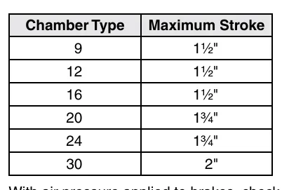
- Ruler — Measure pushrod travel at the clevis pin for comparison with the applicable chamber-specific stroke chart.
The manual-adjustment sequence begins by greasing the cam bracket and spider fittings. The adjuster is then moved until the lining contacts the drum.
A green brake is unground and unburnished. Its initial setting retains slight wheel drag to account for lining irregularities, and further adjustment is mandatory during break-in as the lining seats against the drum.
For burnished brakes, Dexter's detailed procedure specifies backing off to 0.010-inch lining-to-drum clearance and applying the brakes at 80–90 psi. The earlier component description gives an approximate manual-adjuster clearance of 0.020–0.030 inch; these are different source contexts, not interchangeable instructions. Values vary by maker.
Adjustment is followed by pushrod-travel, applied lining-contact and release checks. Dexter warns that pressure above 130 psi can cause chamber failure; that warning is not a test-pressure target. Use the chamber-specific stroke chart and the detailed verification procedure rather than judging adjustment only by wheel drag.
How It Works
Prepare the mechanism before setting clearance
Begin by greasing the cam bracket and spider fittings, then move the adjuster until the lining contacts the drum. Lubrication helps the cam mechanism move freely; binding can interfere with both adjustment and release.
Brake condition determines the setting
A green brake is unground and unburnished, so its initial setting retains slight wheel drag to accommodate lining irregularities, with further adjustment mandatory during break-in as the lining seats. For burnished brakes, Dexter's detailed procedure specifies 0.010 inch clearance; the earlier component description's approximate 0.020–0.030 inch clearance belongs to a different source context and is not interchangeable.
Verify performance under application and release
Apply the brakes at 80–90 psi for this procedure, measure pushrod travel at the clevis pin against the chamber-specific limit, and check applied lining contact and the prescribed applied linkage angle. Release pressure and verify relaxed return rather than accepting wheel drag alone as proof of correct adjustment. Air pressure above 130 psi can cause failure; that warning is not a test-pressure target, and values vary by maker.
Step-by-Step Procedure
0/7 doneDexter detailed manual-adjustment values; values vary by maker
| Burnished-brake clearance | 0.010 inch |
| Brake application pressure | 80–90 psi |
| Chamber-failure warning | Air pressure above 130 psi can cause failure |
Figures
Diagnostic Chart
| Symptom | Check | Spec / Expected | Likely cause & fix |
|---|---|---|---|
| A green brake needs readjustment as it breaks in. | Confirm that the lining is unground and unburnished, assess the initial slight drag, and repeat the required adjustment and verification as the lining seats. | Retain slight initial wheel drag; further adjustment during break-in is mandatory. | Lining irregularities wear into drum contact, changing the initial fit. Basis: 9-15k complete service manual |
| A burnished brake was set using an approximate component-description clearance. | Confirm which source procedure was followed and reset using the applicable detailed adjustment instructions. | Dexter detailed burnished-brake clearance: 0.010 inch. The approximate 0.020–0.030 inch value is from a different source context. | A descriptive clearance was substituted for the detailed procedure's adjustment requirement. Basis: 9-15k complete service manual |
| Wheel drag seems acceptable, but applied-brake verification is incomplete. | Confirm application pressure, measure travel at the clevis pin, compare it with the chamber-specific stroke chart, and check applied contact and linkage angle using the detailed procedure. | Apply at 80–90 psi; obtain the chamber-specific travel limit, applied linkage angle and feeler-gauge criterion from the applicable source procedure. | Wheel drag alone does not establish acceptable travel, applied contact or linkage geometry. Basis: 9-15k complete service manual |
| The brake remains dragging after pressure is released. | Secure the trailer, confirm pressure releases, and inspect for tight adjustment, binding cam or linkage components, and impaired return action before further adjustment. | Do not accept persistent binding as normal release behavior; verify the applicable manufacturer's release requirements. | Residual pressure, insufficient clearance, mechanical binding or damaged return components may prevent release. Basis: General shop practice |
At the Bay: Diagnose the Case
CASE 1 / 4
A green brake needs readjustment as it breaks in.
- Test
- Compare
- Correct
Select the next check
Basis: 9-15k complete service manual. A likely cause is a hypothesis; confirm it with the applicable service procedure before repair.
Common Bay Mistakes
- ✕ Applying burnished-brake clearance instructions to a green brake.
- ✕ Skipping mandatory green-brake readjustment during break-in.
- ✕ Treating approximate component-description clearance as the detailed adjustment instruction.
- ✕ Using the chamber-failure warning as a pressure target or wheel drag as the sole acceptance check.
Quick Check
Practice only — not scored.
Plan the Service Sequence
Planning practice only. Follow the applicable manufacturer's instructions, employer safety program and qualified supervision on real equipment.
Plan the first action. Compare the service steps with the bay mistakes.
Hands-on: Shop Test Equipment
Air Brake Board — Leakdown & Pushrod Stroke
Supply and service gauges, gladhand controls, pushrod stroke ruler (Type 30 chamber)
🛠 Equip your bay for this test →Symptom: Pre-trip inspection.
Spec limits used
- 2 in — Type 30 max pushrod stroke (Dexter 9-15K service manual, p.52)
- 80–90 psi — Adjustment test application pressure (Dexter 9-15K service manual, p.51)
- 130 psi — Never exceed (chamber failure risk) (Dexter 9-15K service manual, p.51)
- illustrative only — Leakdown pass limit (General shop practice)
Simulated readings for practice. Always follow the manufacturer's procedure and values on a real trailer.
Source: 9-15k complete service manual — 45, 51-52