Verify Stroke, Contact, Geometry and Release
- Select the correct chamber-specific stroke limit and measure travel at the clevis pin.
- Evaluate applied lining contact and pushrod-to-adjuster geometry separately.
- Confirm complete release without treating acceptable stroke as proof of correct adjustment.
- Wheel chocks — Secure the trailer against movement before brake application and release checks.
- Steel rule — Measure clevis-pin movement from the released position to the applied position.
- Feeler gauge set — Use the 0.010-inch blade to check doubtful lining-to-drum contact during application.
- Angle gauge — Check the angle between the pushrod and slack adjuster with the brake applied.
- Inspection light — Illuminate accessible lining contact areas and linkage while keeping hands clear of moving components.
Pushrod travel is checked at the clevis pin while the brake is applied. Select the limit for the chamber type rather than using the same allowable stroke for every chamber.
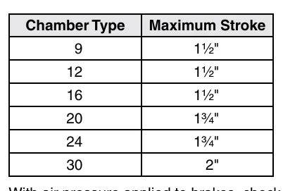
Dexter's chart lists maximum stroke of 1 1/2 inches for types 9, 12 and 16; 1 3/4 inches for types 20 and 24; and 2 inches for type 30. These are the supplied chart's values, and values vary by maker and application.
Applied lining contact should approach the entire drum-contact area. Dexter specifies a 0.010-inch feeler gauge when contact is doubtful; it should not enter between the lining and drum during application. The applied pushrod-to-adjuster angle should be approximately 90 degrees, within 5 degrees. Values vary by maker.
After the applied checks, release pressure and confirm that all brakes return to their normal relaxed position. Stroke, contact, linkage geometry and release are separate checks in the source; a satisfactory reading in one does not replace the others.
How It Works
Stroke measures travel, not overall brake condition
Identify the chamber type, then measure travel at the clevis pin with the brake applied at the preceding procedure's specified pressure. Dexter lists maximum stroke of 1 1/2 inches for types 9, 12 and 16; 1 3/4 inches for types 20 and 24; and 2 inches for type 30, but values vary by maker and application. Excessive travel can indicate clearance or linkage problems, while acceptable travel does not establish correct contact, geometry or release.
Contact and geometry determine how force is delivered
Applied lining contact should approach the entire drum-contact area; when contact is doubtful, Dexter specifies that a 0.010-inch feeler gauge should not enter between the lining and drum during application. Uneven contact concentrates load and heat rather than distributing braking work across the lining. The applied pushrod-to-adjuster angle should be approximately 90 degrees, within 5 degrees; this relationship affects how effectively pushrod force produces turning effort, and the applicable maker's requirements must be verified.
Release is an independent functional check
After the applied checks, release brake pressure and confirm that every brake returns to its normal relaxed position. Binding linkage or a return fault can leave a brake dragging even when applied stroke appears satisfactory. Drag generates heat and accelerates wear, so a brake must not be accepted on stroke alone.
Step-by-Step Procedure
0/6 doneDexter post-adjustment checks; values vary by maker
| Chamber types 9, 12 and 16 | Maximum stroke: 1 1/2 inches |
| Chamber types 20 and 24 | Maximum stroke: 1 3/4 inches |
| Chamber type 30 | Maximum stroke: 2 inches |
| Applied lining contact | Approach 100%; a 0.010-inch feeler gauge should not fit |
| Applied pushrod-to-adjuster angle | Approximately 90 degrees ±5 degrees |
Figures
Diagnostic Chart
| Symptom | Check | Spec / Expected | Likely cause & fix |
|---|---|---|---|
| Measured pushrod travel appears excessive. | Identify the chamber type and verify the applicable chart before comparing clevis-pin travel measured at the preceding procedure's specified application pressure. | Dexter maximum stroke: 1 1/2 inches for types 9, 12 and 16; 1 3/4 inches for types 20 and 24; 2 inches for type 30. Values vary by maker and application. | The wrong chamber limit may have been selected; a confirmed excess requires investigation of clearance and linkage condition. Basis: 9-15k complete service manual |
| Stroke is acceptable, but lining contact is doubtful. | Inspect accessible lining-to-drum contact with the brake applied and test doubtful contact with the specified feeler gauge. | Contact should approach the entire drum-contact area. A 0.010-inch feeler gauge should not enter between the lining and drum during application. | Uneven seating, wear or component distortion may prevent broad contact; acceptable stroke does not exclude these conditions. Basis: 9-15k complete service manual |
| The applied pushrod and slack adjuster appear poorly aligned. | Measure their angle while the brake is applied rather than judging geometry in the relaxed position. | Approximately 90 degrees, within 5 degrees. Values vary by maker. | Incorrect linkage setup or component mismatch may place the applied linkage outside the required geometry. Basis: 9-15k complete service manual |
| A brake remains displaced after pressure is released. | Confirm release of brake pressure and observe whether every brake returns to its normal relaxed position before investigating the affected mechanism. | All brakes must return to their normal relaxed position after release. | Retained pressure, binding linkage or a return-mechanism fault may prevent full relaxation. Basis: 9-15k complete service manual |
At the Bay: Diagnose the Case
CASE 1 / 4
Measured pushrod travel appears excessive.
- Test
- Compare
- Correct
Select the next check
Basis: 9-15k complete service manual. A likely cause is a hypothesis; confirm it with the applicable service procedure before repair.
Common Bay Mistakes
- ✕ Applying a chamber limit without identifying the chamber and applicable maker's chart.
- ✕ Substituting a guessed application pressure for the preceding procedure's requirement.
- ✕ Accepting stroke while skipping contact and applied-angle checks.
- ✕ Finishing the inspection without confirming every brake releases.
Quick Check
Practice only — not scored.
Plan the Service Sequence
Planning practice only. Follow the applicable manufacturer's instructions, employer safety program and qualified supervision on real equipment.
Plan the first action. Compare the service steps with the bay mistakes.
Hands-on: Shop Test Equipment
Air Brake Board — Leakdown & Pushrod Stroke
Supply and service gauges, gladhand controls, pushrod stroke ruler (Type 30 chamber)
🛠 Equip your bay for this test →Symptom: Pre-trip inspection.
Spec limits used
- 2 in — Type 30 max pushrod stroke (Dexter 9-15K service manual, p.52)
- 80–90 psi — Adjustment test application pressure (Dexter 9-15K service manual, p.51)
- 130 psi — Never exceed (chamber failure risk) (Dexter 9-15K service manual, p.51)
- illustrative only — Leakdown pass limit (General shop practice)
Simulated readings for practice. Always follow the manufacturer's procedure and values on a real trailer.
Source: 9-15k complete service manual — 51-52