Select Wire Size and Protect Connections
- Select minimum copper wire size from the applicable manufacturer's chart.
- Explain how wire damage and connection resistance reduce brake performance.
- Inspect, repair, and seal brake-wiring connections.
- Tape measure — Determine the hitch-to-axle distance required by the applicable chart.
- Digital multimeter — Check circuit continuity with power isolated and compare voltage across wiring and connections during controlled brake operation.
- Wire stripper and cutter — Remove damaged wire ends and strip insulation without nicking conductors.
- Terminal crimping tool — Secure replacement terminals using tooling matched to the connector and wire.
- Heat gun — Shrink sealable connection coverings according to the connection product's instructions.
Brake hookup wire selection depends on the application described by the manufacturer. Read the chart headings carefully: the supplied chart uses the number of brakes and the hitch-to-axle distance, and specifies copper hookup wire.
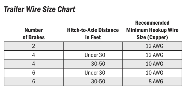
The Dexter chart lists minimum sizes for its applications, not a universal trailer wiring rule. For example, four brakes with a hitch-to-axle distance under 30 feet use a listed minimum of 12 AWG copper, while the 30–50-foot row lists 10 AWG. Values vary by maker.
Insufficient wire size, broken wires, and poor electrical connections are listed causes of low voltage and current at the brakes. Wire selection and connection condition therefore belong in the same electrical inspection.
Loose or corroded connectors increase resistance and reduce the voltage available to the brake magnets. Seal brake-wiring connection points to help prevent corrosion, and properly reconnect and seal wires after testing.
How It Works
Chart selection comes before wire selection
Use the chart applicable to the installed equipment, and read its headings before selecting wire. The supplied Dexter chart uses the number of brakes and hitch-to-axle distance to specify minimum copper hookup sizes; axle count is not a substitute for brake count. Its values are application-specific minimums, not a universal trailer wiring rule.
Wire and connectors share the electrical load
Insufficient wire size, broken conductors, and poor connections can all restrict current delivery to the brake magnets. Added resistance causes voltage loss along the circuit and can generate heat at damaged or loose connections. Correct wire size cannot compensate for a high-resistance connection.
Repair the connection before sealing it
Loose or corroded connectors reduce the voltage available to the brake magnets, so inspect connection condition along with conductor size. Restore a sound electrical and mechanical connection before sealing; covering corrosion does not remove its resistance. Properly reconnect and seal wires disturbed during testing to help prevent moisture-driven corrosion.
Step-by-Step Procedure
0/6 doneDexter minimum copper hookup sizes; values vary by maker
| Two brakes; distance not specified in this chart | 12 AWG |
| Four brakes; under 30 ft | 12 AWG |
| Four brakes; 30–50 ft | 10 AWG |
| Six brakes; under 30 ft | 10 AWG |
| Six brakes; 30–50 ft | 8 AWG |
Figures
Diagnostic Chart
| Symptom | Check | Spec / Expected | Likely cause & fix |
|---|---|---|---|
| Weak braking with suspected undersized hookup wire | Identify the equipment manufacturer, count the brakes, determine the chart's hitch-to-axle distance, and compare the installed copper wire with the matching row. | Dexter lists four brakes under 30 feet at a minimum of 12 AWG copper; its 30–50-foot row lists 10 AWG. Use these values only for the applicable application. | Insufficient wire size can cause low voltage and current at the brakes. Basis: LDServiceOnline |
| Low brake performance with loose or corroded connectors | Inspect terminals and splices for looseness, corrosion, and broken conductors; correct the defects and seal the repaired connection points. | Brake-wiring connection points should be sealed, and wires disturbed during testing should be properly reconnected and sealed. | Loose or corroded connections increase resistance and reduce voltage available to the brake magnets. Basis: LDServiceOnline |
| A continuity check passes, but braking remains weak | With the trailer secured and the brakes operated under controlled conditions, use a multimeter to check voltage loss across suspect connections and wire sections. | Compare results with the installed equipment manufacturer's electrical test procedure; do not infer loaded circuit health from continuity alone. | A damaged or corroded path may conduct the meter's test current yet develop excessive voltage loss under operating load. Basis: General shop practice |
| Intermittent braking near a previously repaired splice | Isolate power before handling the splice. Inspect for loose terminal grip, damaged strands, corrosion beneath insulation, and an incomplete seal. | Use repair materials and tooling compatible with the conductor and connector, then verify the connection and restore its seal. | Poor terminal retention or damaged strands can interrupt current as the harness moves; moisture entry can progressively increase resistance. Basis: General shop practice |
At the Bay: Diagnose the Case
CASE 1 / 4
Weak braking with suspected undersized hookup wire
- Test
- Compare
- Correct
Select the next check
Basis: LDServiceOnline. A likely cause is a hypothesis; confirm it with the applicable service procedure before repair.
Common Bay Mistakes
- ✕ Substituting axle count for the chart's brake count.
- ✕ Using total trailer length instead of hitch-to-axle distance.
- ✕ Treating Dexter minimums as universal wiring requirements.
- ✕ Sealing a loose or corroded splice without repairing it.
Quick Check
Practice only — not scored.
Plan the Service Sequence
Planning practice only. Follow the applicable manufacturer's instructions, employer safety program and qualified supervision on real equipment.
Plan the first action. Compare the service steps with the bay mistakes.
Hands-on: Test Bench Practice
Symptom: Healthy trailer. Learn what good readings look like.
Tap a point to place the red probe.
Good system: ~12.6 V at pins, 3.2 Ω across a 12×2-inch magnet (unplugged), 3.0 A per magnet at 12 V full gain, and at least 10.5 V at the magnet — the chart values from the axle manuals.
Hands-on: Shop Test Equipment
IPA #9107B Electric Brake Force Meter
Plugs into the truck's 7-way socket on a 25 ft cable; simulates a trailer load and shows controller output on 10 blue LEDs
🛠 Equip your bay for this test →Symptom: Customer wants the truck checked before buying a trailer.
Spec limits used
- 1–10, each 1.0–1.5 V — Gain LEDs (IPA #9107B manual, p.5)
- 15 s — Max time holding brake pedal (IPA #9107B manual, p.4)
- set-up step 5 — Connect the 9-pin only after the engine is running (IPA #9107B manual, p.3)
- hold brake pedal during ECU detection — 2016–2017 'Trailer Connected' not shown (IPA #9107B manual, p.3)
- faulty brake control module or relay — ECU light never lights on a vehicle with a controller (IPA #9107B manual, p.5)
Simulated readings for practice. Always follow the manufacturer's procedure and values on a real trailer.
Hands-on: Wire-Trace Overlay
Pin 2 · Blue
Electric brakes
- Left and right brake magnets
- Breakaway switch output
Check points
- Two brakes draw about 6.0 A (3.0 A per magnet) at 12 V full gain.
- Unplugged: 3.2 Ω per magnet; at least 10.5 V at each magnet under load.
Common failures
- Open magnet: about half the expected current and a pull to one side.
- Shorted magnet: very low resistance and controller overload.
- Wire chafed where it drops to the axle.
Colors shown are the most common RV harness colors; makers vary — always verify against the trailer's wiring diagram.
Source: LDServiceOnline — 12, 22-23