Understand Electric Brake and Controller Action
- Trace current from the controller through the brake's mechanical action.
- Explain how modulation controls trailer braking force.
- Recognize synchronization problems and verify coordinated braking safely.
- Digital multimeter — Check electrical input at the controller output and brake wiring using the manufacturer's test procedure.
- DC clamp ammeter — Observe brake-circuit current during controlled brake application.
- Inspection light — Inspect accessible wiring and exposed brake components during a safely supported inspection.
- Brake adjusting tool — Check and correct shoe adjustment according to the brake manufacturer's procedure.
- Wheel chocks — Prevent unintended trailer movement during stationary checks.
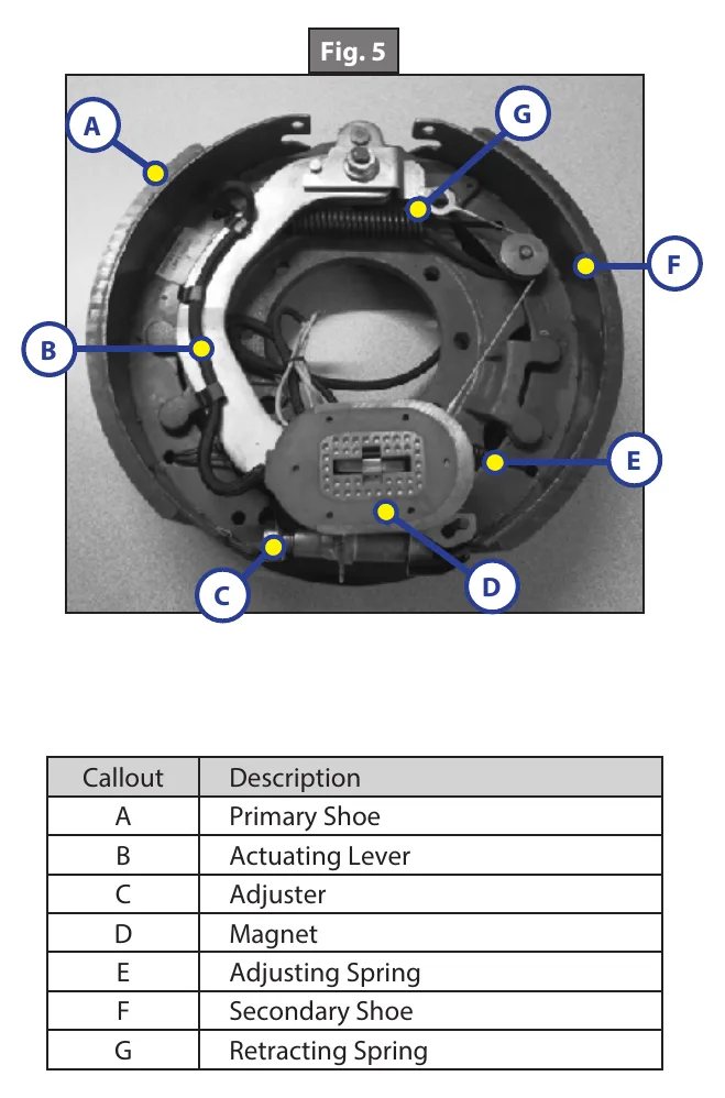
An electric trailer drum brake uses an electromagnet to initiate braking. The controller supplies current to the magnet, which is attracted to the rotating armature surface of the drum.
Magnet attraction moves the actuating lever in the drum's direction of rotation. The lever's cam pushes the primary shoe outward, and force through the adjuster brings the secondary shoe into contact with the drum.
Increasing magnet current increases its grip on the armature and increases shoe pressure against the drum. Controller modulation varies the electrical input with brake-pedal pressure or tow-vehicle deceleration instead of immediately applying high output.
The trailer and tow vehicle brakes are intended to work together. Follow the controller manufacturer's setup instructions and verify synchronization by road testing in a clear area; harshness or grabbing can result from poor synchronization, excessive threshold voltage, or brake adjustment problems.
How It Works
From electrical input to shoe application
The controller supplies current to the electromagnet, attracting it to the rotating drum armature surface. Frictional drag at that interface moves the actuating lever in the drum's direction of rotation, and the lever's cam pushes the primary shoe outward. Force passes through the adjuster to bring the secondary shoe against the drum.
Why modulation matters
Increasing magnet current increases grip on the armature and increases shoe pressure against the drum. Modulation varies electrical input with brake-pedal pressure or tow-vehicle deceleration rather than immediately applying high output. This helps braking build progressively instead of delivering an abrupt application that can promote grabbing or sliding.
Synchronization is a combined-system requirement
The trailer and tow vehicle brakes are intended to work together, so controller setup must follow the controller manufacturer's instructions. Verify synchronization through the prescribed road test in an area clear of traffic and pedestrians. Relying on only the tow vehicle brakes or only the trailer brakes can lead to wheel lockup, sliding, and loss of control.
Step-by-Step Procedure
0/6 doneFigures
Diagnostic Chart
| Symptom | Check | Spec / Expected | Likely cause & fix |
|---|---|---|---|
| Trailer brakes grab or apply harshly. | Review controller setup and threshold settings against the controller manufacturer's instructions, check brake adjustment, and verify synchronization through the prescribed clear-area road test. | Harshness or grabbing can result from poor synchronization, excessive threshold voltage, or brake adjustment problems; no numeric setting is supplied. | Controller input or shoe adjustment may produce an abrupt application rather than coordinated braking. Basis: LDServiceOnline |
| Trailer brakes do not respond to a brake command. | With the trailer secured, verify controller activation and trace electrical input through accessible wiring and connections to the magnets using the manufacturer's procedure. | Use the applicable manufacturer's electrical test criteria; this lesson supplies no numeric electrical acceptance limits. | Loss of power, an open connection, a poor return path, or a controller fault may prevent magnet energization. Basis: General shop practice |
| Electrical input is present, but braking remains weak. | Inspect the magnet-to-armature contact condition, lever movement, shoe condition, and adjuster force path using approved disassembly and support procedures. | Evaluate component condition and adjustment against the brake manufacturer's service instructions; no wear limits are supplied here. | Contamination, damaged contact surfaces, binding linkage, or incorrect adjustment may prevent electrical input from becoming effective shoe pressure. Basis: General shop practice |
| Tow vehicle and trailer braking do not feel coordinated. | Follow the controller manufacturer's setup instructions and perform the prescribed synchronization road test away from traffic and pedestrians. | Trailer and tow vehicle brakes must work together; do not rely on either system alone to stop the combined load. | Poor synchronization can prevent the braking systems from sharing the stopping task appropriately. Basis: LDServiceOnline |
At the Bay: Diagnose the Case
CASE 1 / 4
Trailer brakes grab or apply harshly.
- Test
- Compare
- Correct
Select the next check
Basis: LDServiceOnline. A likely cause is a hypothesis; confirm it with the applicable service procedure before repair.
Common Bay Mistakes
- ✕ Mistaking magnet energization for proof of effective shoe application.
- ✕ Increasing controller output to conceal a mechanical brake problem.
- ✕ Treating grabbing as proof that the controller alone is faulty.
- ✕ Testing synchronization near traffic or pedestrians.
Quick Check
Practice only — not scored.
Plan the Service Sequence
Planning practice only. Follow the applicable manufacturer's instructions, employer safety program and qualified supervision on real equipment.
Plan the first action. Compare the service steps with the bay mistakes.
Hands-on: Test Bench Practice
Symptom: Healthy trailer. Learn what good readings look like.
Tap a point to place the red probe.
Good system: ~12.6 V at pins, 3.2 Ω across a 12×2-inch magnet (unplugged), 3.0 A per magnet at 12 V full gain, and at least 10.5 V at the magnet — the chart values from the axle manuals.
Hands-on: Shop Test Equipment
IPA #9107B Electric Brake Force Meter
Plugs into the truck's 7-way socket on a 25 ft cable; simulates a trailer load and shows controller output on 10 blue LEDs
🛠 Equip your bay for this test →Symptom: Customer wants the truck checked before buying a trailer.
Spec limits used
- 1–10, each 1.0–1.5 V — Gain LEDs (IPA #9107B manual, p.5)
- 15 s — Max time holding brake pedal (IPA #9107B manual, p.4)
- set-up step 5 — Connect the 9-pin only after the engine is running (IPA #9107B manual, p.3)
- hold brake pedal during ECU detection — 2016–2017 'Trailer Connected' not shown (IPA #9107B manual, p.3)
- faulty brake control module or relay — ECU light never lights on a vehicle with a controller (IPA #9107B manual, p.5)
Simulated readings for practice. Always follow the manufacturer's procedure and values on a real trailer.
Hands-on: Wire-Trace Overlay
Pin 2 · Blue
Electric brakes
- Left and right brake magnets
- Breakaway switch output
Check points
- Two brakes draw about 6.0 A (3.0 A per magnet) at 12 V full gain.
- Unplugged: 3.2 Ω per magnet; at least 10.5 V at each magnet under load.
Common failures
- Open magnet: about half the expected current and a pull to one side.
- Shorted magnet: very low resistance and controller overload.
- Wire chafed where it drops to the axle.
Colors shown are the most common RV harness colors; makers vary — always verify against the trailer's wiring diagram.
Source: LDServiceOnline — 6-8, 12-13