Measure System and Individual Magnet Current
- Connect an ammeter safely for system and individual magnet testing.
- Compare current readings with the installed brake manufacturer's chart.
- Isolate current faults and restore sealed wiring after testing.
- Ammeter — Measure current in series; verify sufficient capacity and correct polarity before connecting.
- Voltmeter — Check supply voltage and voltage loss when interpreting unexpected current readings.
- Insulated test leads — Make secure connections at the controller output or separated magnet connector without contacting adjacent terminals.
- Wire stripper and crimper — Restore damaged wire ends and secure appropriate sealed repair connections after testing.
- Heat gun — Seal heat-shrink repair materials where the wiring repair calls for them.
System amperage is the current flowing when all brake magnets are energized. Current varies with voltage, so interpret a current reading with the electrical test conditions in mind.
The source describes measuring total brake current by disconnecting the controller's brake-output wire and inserting an ammeter in series. The tow vehicle engine should be running with the trailer connected, and the ammeter must have sufficient capacity and correct polarity.
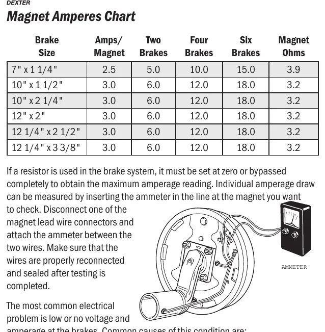
For an individual magnet, disconnect a magnet lead connector and insert the ammeter between the separated wires. If a system resistor is fitted, the source requires it to be set at zero or bypassed for the maximum-current check; reconnect and seal the wiring after testing.
Use the brake-size row rather than assuming every magnet has the same draw. Dexter lists 3.0 A per magnet and 12.0 A for four 12 x 2-inch brakes, while its smaller 7 x 1¼-inch brake row has different values. Values vary by maker.
How It Works
Current readings depend on test conditions
System amperage is the current flowing when all brake magnets are energized, and it changes with the voltage applied. Keep the trailer connected and the tow vehicle engine running during the source-described check; if fitted, set the system resistor at zero or bypass it for the maximum-current check. Low applied voltage or resistance in connections can reduce current without a failed magnet.
Series measurement puts the meter in the current path
For system current, disconnect the controller's brake-output wire and insert the ammeter in series so brake current passes through the meter. For an individual magnet, disconnect its lead connector and insert the meter between the separated wires. Verify capacity and polarity before connecting; placing an ammeter across a supply instead of in series can create a damaging short circuit.
Use the correct chart and finish the repair
Dexter lists 3.0 A per magnet and 12.0 A for four 12 x 2-inch brakes, but these values are not universal. Use the chart for the installed brake size and manufacturer, then compare individual readings when the system reading needs investigation. Reconnect and seal disturbed wiring because moisture and corrosion can increase connection resistance and compromise future braking.
Step-by-Step Procedure
0/7 doneDexter current chart for 12 x 2-inch brakes; values vary by maker
| Per magnet | 3.0 A |
| Four brakes | 12.0 A |
Figures
Diagnostic Chart
| Symptom | Check | Spec / Expected | Likely cause & fix |
|---|---|---|---|
| Total system current appears low. | Confirm brake size and manufacturer, trailer connection, running engine, and energized magnets; verify the resistor setting if fitted before judging the reading. | Dexter four 12 x 2-inch brakes: 12.0 A. For the maximum-current check, the system resistor must be at zero or bypassed if fitted. | Incorrect test conditions, an unsuitable comparison chart, or reduced current in a brake branch can produce a low result. Basis: LDServiceOnline |
| An individual magnet reading does not match the chart. | Insert the ammeter at the disconnected magnet lead connector and compare the reading with the chart for that brake size and maker. | Dexter 12 x 2-inch brakes: 3.0 A per magnet; values vary by maker. | The wrong chart may have been selected, or the magnet circuit may require further electrical diagnosis. Basis: LDServiceOnline |
| A magnet draws less current than comparable magnets under matched conditions. | Inspect connectors and grounds, compare voltage at the affected magnet with the supply, and check for voltage loss across suspect connections while energized. | Use the applicable manufacturer current chart; this lesson provides no voltage-drop acceptance limit. | Corroded terminals, loose connections, damaged conductors, or an internal magnet fault can restrict current. Basis: General shop practice |
| The ammeter overloads or indicates incorrect polarity. | Stop the test and verify meter capacity, lead placement, polarity, and series connection before reconnecting. | The ammeter must have sufficient capacity and correct polarity. | Insufficient capacity or incorrect polarity can damage the meter. Basis: LDServiceOnline |
At the Bay: Diagnose the Case
CASE 1 / 4
Total system current appears low.
- Test
- Compare
- Correct
Select the next check
Basis: LDServiceOnline. A likely cause is a hypothesis; confirm it with the applicable service procedure before repair.
Common Bay Mistakes
- ✕ Connecting the ammeter across the supply instead of in series.
- ✕ Condemning a magnet without considering applied voltage.
- ✕ Applying the Dexter chart to every brake size and maker.
- ✕ Leaving test connections loose or unsealed.
Quick Check
Practice only — not scored.
Plan the Service Sequence
Planning practice only. Follow the applicable manufacturer's instructions, employer safety program and qualified supervision on real equipment.
Plan the first action. Compare the service steps with the bay mistakes.
Hands-on: Test Bench Practice
Symptom: Healthy trailer. Learn what good readings look like.
Tap a point to place the red probe.
Good system: ~12.6 V at pins, 3.2 Ω across a 12×2-inch magnet (unplugged), 3.0 A per magnet at 12 V full gain, and at least 10.5 V at the magnet — the chart values from the axle manuals.
Hands-on: Shop Test Equipment
IPA #9107B Electric Brake Force Meter
Plugs into the truck's 7-way socket on a 25 ft cable; simulates a trailer load and shows controller output on 10 blue LEDs
🛠 Equip your bay for this test →Symptom: Customer wants the truck checked before buying a trailer.
Spec limits used
- 1–10, each 1.0–1.5 V — Gain LEDs (IPA #9107B manual, p.5)
- 15 s — Max time holding brake pedal (IPA #9107B manual, p.4)
- set-up step 5 — Connect the 9-pin only after the engine is running (IPA #9107B manual, p.3)
- hold brake pedal during ECU detection — 2016–2017 'Trailer Connected' not shown (IPA #9107B manual, p.3)
- faulty brake control module or relay — ECU light never lights on a vehicle with a controller (IPA #9107B manual, p.5)
Simulated readings for practice. Always follow the manufacturer's procedure and values on a real trailer.
Hands-on: Wire-Trace Overlay
Pin 2 · Blue
Electric brakes
- Left and right brake magnets
- Breakaway switch output
Check points
- Two brakes draw about 6.0 A (3.0 A per magnet) at 12 V full gain.
- Unplugged: 3.2 Ω per magnet; at least 10.5 V at each magnet under load.
Common failures
- Open magnet: about half the expected current and a pull to one side.
- Shorted magnet: very low resistance and controller overload.
- Wire chafed where it drops to the axle.
Colors shown are the most common RV harness colors; makers vary — always verify against the trailer's wiring diagram.
Source: LDServiceOnline — 21-22