Recognize Frame Attachment, Clearance and Alignment
- Recognize frame members, mounting brackets and reinforcement needs.
- Distinguish bump, tire-to-tire and fender clearance.
- Verify axle alignment using a checked reference and applicable manufacturer criteria.
- Inspection light — Illuminate mounting brackets, frame connections and possible contact marks.
- Tape measure — Check clearances and compare layout measurements using consistent reference points.
- Straightedge — Help establish reference lines and inspect local distortion around attachments.
- Framing square — Help check a proposed cross-member reference against the established frame centerline.
- Chalk line — Mark the trailer's longitudinal centerline for axle layout checks.
- Plumb bob — Transfer frame and wheel-center reference locations to a suitable layout surface.
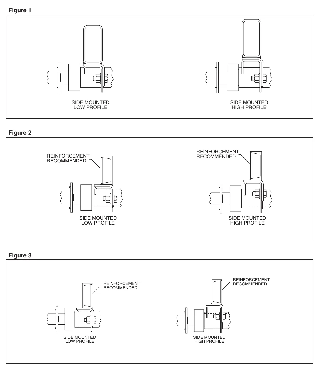
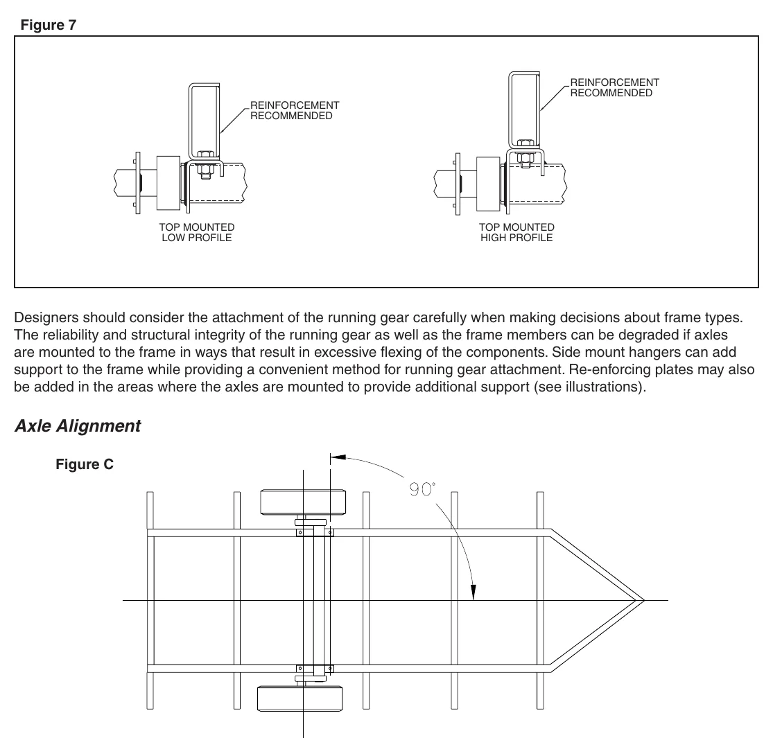
Running-gear attachment affects both axle and frame integrity. Excessive flexing at an unsuitable mounting arrangement can reduce reliability. The source illustrates side-mounted and top-mounted brackets and identifies locations where reinforcement is recommended.
Bump clearance is the space needed between the axle and frame for upward wheel movement without axle-to-frame contact. Tire and fender clearance are separate considerations. Dexter specifies at least 1 inch between tires under any loading condition and 3 inches above the tire at full load for fender clearance in the cited application guidance. Values vary by maker and installation.
An axle should be perpendicular to the trailer's longitudinal centerline. Incorrect alignment can cause poor tracking and accelerated tire wear. Multiple axles must also be aligned with one another.
Dexter's application guidance specifies perpendicular alignment within plus or minus one-half degree and multiple-axle parallelism within one-sixteenth inch measured at wheel centers. These values vary by maker and application. A front cross member should be used as a layout reference only after its squareness to the frame centerline has been checked.
How It Works
Attachment strength depends on the load path
Running-gear brackets transfer road and suspension forces into the frame, so an unsuitable mounting arrangement can allow excessive flexing and reduce reliability. Distinguish the brackets from the structural frame members, then compare the side-mounted and top-mounted illustrations to locate the recommended reinforcement rather than assuming either arrangement is suitable without review.
Clearance must accommodate movement
Bump clearance allows upward wheel movement without axle-to-frame contact; tire-to-tire and tire-to-fender clearance address different contact risks and must be checked separately. The cited Dexter guidance specifies at least 1 inch between tires under any loading condition and 3 inches above the tire at full load for fender clearance. These values vary by maker and installation and do not establish a bump-clearance requirement.
Alignment requires a trustworthy reference
An axle should be perpendicular to the trailer's longitudinal centerline, and multiple axles must also be aligned with one another; errors can make tires scrub and cause poor tracking and accelerated wear. Dexter's cited criteria are perpendicular alignment within plus or minus one-half degree and multiple-axle parallelism within one-sixteenth inch measured at wheel centers, subject to the applicable maker and application. Verify a proposed front cross member is square to the frame centerline before using it for layout, or its error will be transferred into axle placement.
Step-by-Step Procedure
0/7 doneDexter application guidance; values vary by maker and installation
| Tire-to-tire clearance | At least 1 inch under any loading condition |
| Fender clearance | 3 inches above the tire at full load |
| Axle perpendicular alignment | Within ±0.5 degree |
| Multiple-axle parallelism | Within 1/16 inch, measured at wheel centers |
Figures
Diagnostic Chart
| Symptom | Check | Spec / Expected | Likely cause & fix |
|---|---|---|---|
| Excessive flexing around a running-gear attachment. | Identify the frame members and brackets, compare the mounting arrangement with the applicable illustrations, and locate areas where reinforcement is recommended. | Use the applicable attachment guidance and illustrated reinforcement locations; the lesson provides no reinforcement dimensions. | An unsuitable mounting arrangement may concentrate loads and allow excessive frame or bracket flexing. Basis: applications-manual-(lit-008-00) |
| Axle-to-frame contact marks or suspected bottoming. | Evaluate axle-to-frame space through the applicable suspension movement conditions; do not substitute a tire or fender clearance measurement. | Bump clearance must permit upward wheel movement without axle-to-frame contact; no numerical bump-clearance value is supplied. | Insufficient bump clearance allows the moving axle to strike the frame. Basis: applications-manual-(lit-008-00) |
| Tire-to-tire rubbing or tire contact with a fender. | Check tire separation under the relevant loading conditions and measure clearance above the tire at full load, using the applicable manufacturer's requirements. | Cited Dexter guidance: At least 1 inch under any loading condition for tire-to-tire clearance; 3 inches above the tire at full load for fender clearance. Values vary by maker and installation. | Available clearance may be inadequate as loading changes tire position relative to adjacent tires or the fender. Basis: applications-manual-(lit-008-00) |
| Poor tracking or accelerated tire wear. | Establish the longitudinal centerline, verify any cross-member reference is square, and check axle perpendicularity and multiple-axle parallelism at wheel centers. | Cited Dexter guidance: Within ±0.5 degree for axle perpendicular alignment; Within 1/16 inch, measured at wheel centers for multiple-axle parallelism. Confirm applicability before use. | Axle misalignment, including error copied from an unchecked cross member, can cause poor tracking and tire scrub. Basis: applications-manual-(lit-008-00) |
At the Bay: Diagnose the Case
CASE 1 / 4
Excessive flexing around a running-gear attachment.
- Test
- Compare
- Correct
Select the next check
Basis: applications-manual-(lit-008-00). A likely cause is a hypothesis; confirm it with the applicable service procedure before repair.
Common Bay Mistakes
- ✕ Treating an unchecked cross member as a square layout reference.
- ✕ Using fender clearance as proof of adequate bump clearance.
- ✕ Treating Dexter example criteria as universal requirements.
- ✕ Assuming mounting brackets provide adequate frame support without reviewing reinforcement guidance.
Quick Check
Practice only — not scored.
Plan the Service Sequence
Planning practice only. Follow the applicable manufacturer's instructions, employer safety program and qualified supervision on real equipment.
Plan the first action. Compare the service steps with the bay mistakes.
Source: applications-manual-(lit-008-00) — 4-20