Recognize Drum and Disc Brake Anatomy
- Identify drum and disc brake friction pairs.
- Trace electric, hydraulic and air drum-brake application mechanisms.
- Distinguish floating-caliper movement from fixed-caliper operation.
- Inspection light — Illuminate shoe ends, application mechanisms and caliper features.
- Inspection mirror — View obscured components without placing fingers in moving mechanisms.
- Wheel chocks — Secure the trailer against rolling before inspection.
- Socket and ratchet set — Remove access hardware only as directed by the applicable service procedure.
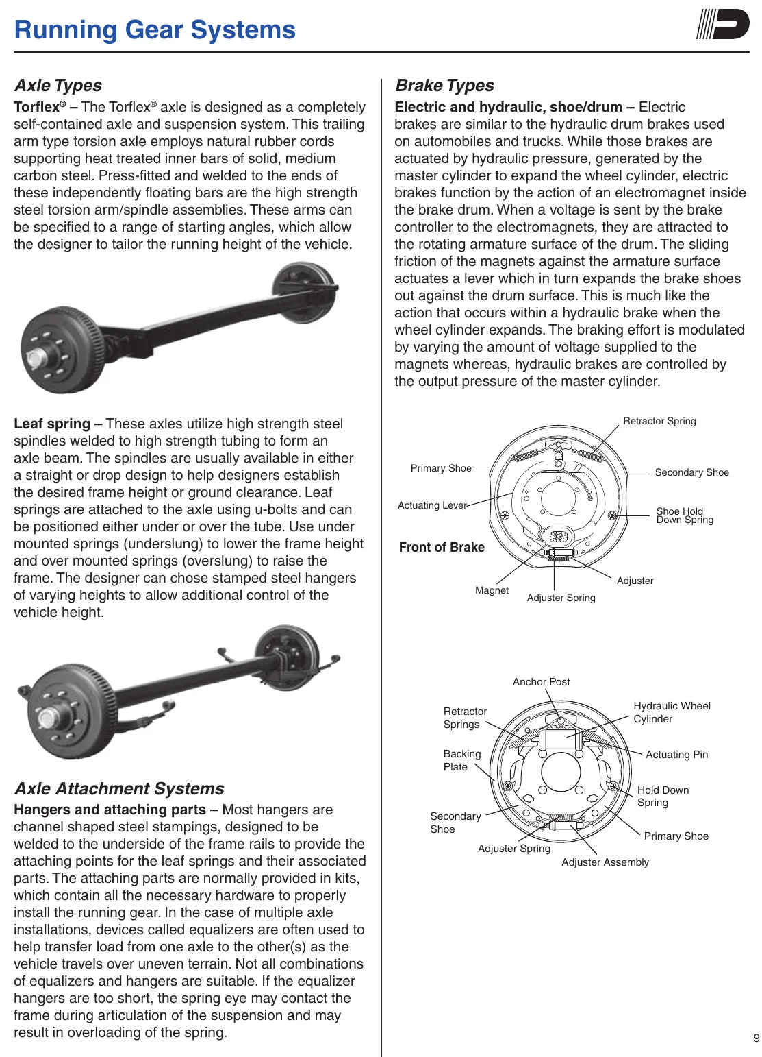
Drum brakes apply shoes against the inside of a rotating drum. The source's component illustrations identify primary and secondary shoes, retractor springs and an adjuster. Electric and hydraulic drum brakes use different mechanisms to apply the shoes.
An electric drum brake uses an electromagnet attracted to the drum's rotating armature surface. Friction moves an actuating lever, which expands the shoes against the drum. Changing the electrical input changes the braking effort.
A hydraulic drum brake uses fluid pressure to operate a wheel cylinder. An air-operated drum brake instead uses a brake chamber and slack adjuster to rotate an S-shaped cam between the shoe ends.
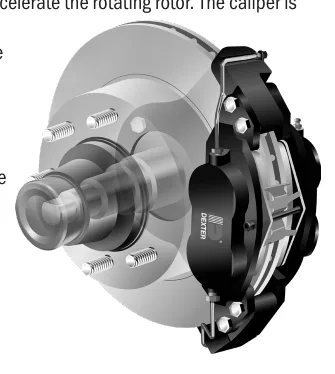
Disc brakes use a rotor in place of the drum. A caliper straddles the rotor and applies friction pads to its sides. The ventilated rotor dissipates heat generated by braking. Floating calipers have pistons on one side and move laterally; fixed calipers use pistons on both sides and remain stationary.
How It Works
Separate friction components from application components
Drum brakes press shoes against the inside of a rotating drum; disc brakes clamp pads against the sides of a rotor. These friction pairs convert motion into heat, while the application mechanism supplies the force that brings them together. The ventilated disc rotor helps dissipate braking heat.
Follow the drum-brake application path
In an electric drum brake, the electromagnet attracts to the rotating armature surface, and friction moves an actuating lever that expands the shoes; changing electrical input changes braking effort. In a hydraulic drum brake, fluid pressure operates a wheel cylinder, while an air drum brake uses a brake chamber and slack adjuster to rotate an S-shaped cam between the shoe ends. Identify primary and secondary shoes, retractor springs and the adjuster separately from the mechanism that applies the shoes.
Recognize caliper operation and inspect safely
A caliper straddles the rotor and applies friction pads to its sides. Floating calipers have pistons on one side and move laterally, whereas fixed calipers have pistons on both sides and remain stationary. Some older linings may contain asbestos, so do not create brake dust with compressed air or dry brushing.
Step-by-Step Procedure
0/6 doneFigures
Diagnostic Chart
| Symptom | Check | Spec / Expected | Likely cause & fix |
|---|---|---|---|
| An electric drum brake is mistaken for a hydraulic drum brake. | Locate the electromagnet and trace its connection through the actuating lever to the shoes. | Electric drum application uses a magnet attracted to the rotating armature surface; friction moves the lever to expand the shoes. | The shared shoe-and-drum friction pair can conceal the difference in application mechanisms. Basis: applications-manual-(lit-008-00) |
| A wheel cylinder is identified as a friction component. | Separate the parts that contact the rotating drum from the part operated by fluid pressure. | The wheel cylinder applies hydraulic drum brakes; the shoes and drum form the friction pair. | The component supplying application force has been confused with the components producing braking friction. Basis: applications-manual-(lit-008-00) |
| An air drum-brake application mechanism cannot be identified. | Trace the brake chamber through the slack adjuster to the S-cam between the shoe ends. | The brake chamber and slack adjuster rotate an S-shaped cam to apply the shoes. | The application path has not been followed from the actuator to the shoe ends. Basis: applications-manual-(lit-008-00) |
| Lateral caliper movement is treated as proof of a fault. | Identify whether the caliper is floating or fixed before interpreting its movement. | Floating calipers move laterally and have pistons on one side; fixed calipers remain stationary and have pistons on both sides. | Normal floating-caliper operation may have been confused with unintended looseness. Basis: applications-manual-(lit-008-00) |
At the Bay: Diagnose the Case
CASE 1 / 4
An electric drum brake is mistaken for a hydraulic drum brake.
- Test
- Compare
- Correct
Select the next check
Basis: applications-manual-(lit-008-00). A likely cause is a hypothesis; confirm it with the applicable service procedure before repair.
Common Bay Mistakes
- ✕ Do not identify drum actuation type from the shoes alone.
- ✕ Do not confuse retractor springs or the adjuster with the application mechanism.
- ✕ Do not assume every caliper should move laterally.
- ✕ Never use compressed air or dry brushing to create brake dust.
Quick Check
Practice only — not scored.
Plan the Service Sequence
Planning practice only. Follow the applicable manufacturer's instructions, employer safety program and qualified supervision on real equipment.
Plan the first action. Compare the service steps with the bay mistakes.
Source: applications-manual-(lit-008-00) — 10-11