Identify Axles, Springs and Suspension Attachments
- Identify axle beams, spindles and suspension attachments by function.
- Distinguish leaf-spring layouts and their required movement.
- Explain how rubber-cord torsion suspension supports load.
- Flashlight — Illuminate spring ends, hangers, spindle arrangements and torsion arms.
- Inspection mirror — View obscured attachment points without placing hands near moving joints.
- Wire brush — Remove loose dirt and rust that conceal component shapes or contact marks.
- Floor jack — Lift at approved locations when needed for inspection; never use the jack alone to support the trailer.
- Jack stands — Support the trailer at approved locations before working beneath it.
- Wheel chocks — Prevent unintended rolling while inspecting the running gear.
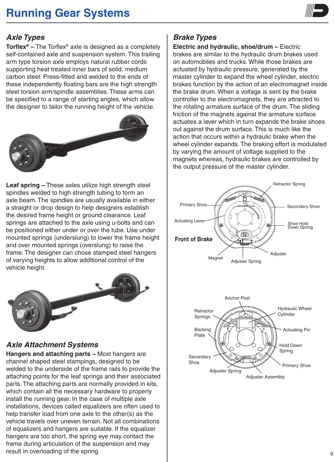
A leaf-spring axle beam consists of steel spindles welded to a tubular beam. Straight and drop spindle arrangements help establish frame height or ground clearance. U-bolts secure the springs to the axle.
Springs mounted below the axle tube form an underslung arrangement that lowers frame height. Springs above the tube form an overslung arrangement that raises it. Hangers provide attachment points on the trailer frame, while their height also influences the installation.
Double-eye springs have an eye at each end. Shackle movement accommodates the spring's length change under load. Slipper springs instead have an eye at one end and a curved sliding end captured by a hanger or equalizer. In multiple-axle arrangements, equalizers help transfer load between axles.
The rubber-cord torsion design described in the source combines the axle and suspension. A spindle-bearing torsion arm acts on an inner steel bar supported by rubber cords. Loading the arm produces resistance in the cords rather than deflecting an external leaf spring.
How It Works
Axle geometry and spring position
A leaf-spring axle beam has steel spindles welded to a tubular beam; straight and drop spindle arrangements help establish frame height or ground clearance. U-bolts secure the springs to the axle: underslung springs sit below the tube and lower frame height, while overslung springs sit above it and raise frame height. Hangers attach the suspension to the frame, and their height also influences the installation.
Spring movement and load transfer
Double-eye springs have eyes at both ends, and shackles accommodate the spring's length change as it deflects under load. Slipper springs have an eye at one end and a curved sliding end captured by a hanger or equalizer; in multiple-axle arrangements, equalizers help transfer load between axles. Spring eyes and equalizers must rotate freely because binding restricts intended movement, concentrates stress and can impair ride or cause spring failure.
Rubber-cord torsion suspension
The rubber-cord torsion design combines the axle and suspension rather than using an external leaf spring. A spindle-bearing torsion arm acts on an inner steel bar supported by rubber cords, so loading the arm produces resistance through deformation of those cords. Identify this design by its torsion arm and integrated suspension arrangement, not by expecting leaf-spring shackles or equalizers.
Step-by-Step Procedure
0/6 doneFigures
Diagnostic Chart
| Symptom | Check | Spec / Expected | Likely cause & fix |
|---|---|---|---|
| Frame height appears inconsistent with the expected leaf-spring layout. | Identify whether the springs sit above or below the axle tube, then identify the spindle arrangement and hanger geometry. | Underslung springs are below the axle tube and lower frame height; overslung springs are above it and raise frame height. Spindle arrangement and hanger height also influence the installation. | The layout may have been misidentified, or its geometry may differ from the expected arrangement. Basis: applications-manual-(lit-008-00) |
| Harsh ride or suspected restricted leaf-spring movement. | With the trailer safely supported, inspect spring-eye joints and equalizers for obstruction or evidence of binding. Assess movement only through a controlled procedure that keeps personnel clear of pinch points. | Spring eyes and equalizers must rotate freely. | Binding prevents intended articulation and can impair ride or cause spring failure. Basis: applications-manual-(lit-008-00) |
| A spring end appears to be missing a shackle. | Identify the spring-end shape before judging the attachment: look for an eye or a curved sliding end captured by a hanger or equalizer. | Double-eye springs use shackle movement to accommodate length change; slipper springs have a captured curved sliding end. | A normal slipper-spring arrangement may be mistaken for an incomplete double-eye arrangement. Basis: applications-manual-(lit-008-00) |
| Rust trails, polished contact marks or apparent shifting at an axle attachment. | Inspect U-bolts, spring seats and adjacent attachment surfaces for looseness, damage or movement. Obtain the applicable manufacturer procedure before tightening or replacing hardware. | The lesson supplies no attachment torque or wear limits; use applicable manufacturer service information. | Loose or damaged attachment hardware can permit relative movement and fretting. Basis: General shop practice |
At the Bay: Diagnose the Case
CASE 1 / 4
Frame height appears inconsistent with the expected leaf-spring layout.
- Test
- Compare
- Correct
Select the next check
Basis: applications-manual-(lit-008-00). A likely cause is a hypothesis; confirm it with the applicable service procedure before repair.
Common Bay Mistakes
- ✕ Do not confuse spring position with spindle drop when identifying frame-height influences.
- ✕ Do not condemn a captured slipper end simply because it has no shackle.
- ✕ Do not treat binding spring eyes or equalizers as normal stiffness.
- ✕ Do not assume missing leaf springs indicate missing parts on rubber-cord torsion running gear.
Quick Check
Practice only — not scored.
Plan the Service Sequence
Planning practice only. Follow the applicable manufacturer's instructions, employer safety program and qualified supervision on real equipment.
Plan the first action. Compare the service steps with the bay mistakes.
Source: applications-manual-(lit-008-00) — 10-13