Trace a Power-Up, Gravity-Down Circuit
- Trace the powered extension path from command to cylinder.
- Explain valve-controlled gravity return without pump operation.
- Separate electrical, flow-path and relief-related faults safely.
- Digital multimeter — Check command signals and circuit continuity using the documented wiring diagram; isolate power before resistance testing.
- Hydraulic pressure gauge with compatible adapters — Observe pressure at an approved test connection using equipment rated for the system; depressurize before installing or removing it.
- Inspection light — Identify manifold markings, valve connections, relief safety wire and any optional flow control.
- Wheel chocks and approved mechanical body supports — Secure the trailer and support the raised body before entering a crush zone; never rely on hydraulic pressure alone.
- Hand wrenches — Service accessible fittings only after the load is safely supported and hydraulic pressure is relieved.
In the documented power-up, gravity-down arrangement, the UP command supplies the starter solenoid and motor. The motor drives the gear pump, so the first diagnostic distinction is whether the command produces motor operation.
Pump flow passes through a check valve and leaves the manifold through port P to extend the cylinder. At the end of stroke or maximum load, the primary relief valve allows flow to bypass to the reservoir.
KTI specifies a 3200 psi primary relief setting for this example. That setting is factory established, values vary by maker, and the source warns against disturbing the safety wire or treating relief adjustment as a pressure-repair method.
The DOWN command energizes the coil of a normally closed two-way valve. Opening that valve lets fluid return to the reservoir. The documented lowering sequence does not call for the motor to drive the pump; an optional manifold flow control can regulate retraction speed.
Read the single-acting wiring diagram by function. In this diagram, UP uses blue or red, DOWN uses green and common uses white. These are the documented diagram assignments, not a universal wire-color convention.
How It Works
Powered extension: command, motor and flow
UP supplies the starter solenoid and motor, and the motor drives the gear pump. Pump flow passes through the check valve and manifold port P to extend the cylinder; motor operation therefore separates an initial electrical-command check from subsequent hydraulic checks. Motor sound alone does not prove that useful flow or pressure reaches the cylinder.
Relief protection is not a repair adjustment
At the end of stroke or maximum load, the primary relief valve provides a bypass to the reservoir. The documented KTI example uses a factory-established 3200 psi setting, but values vary by maker. Bypass flow limits pressure and converts energy into heat, so do not hold the command unnecessarily against a stopped cylinder or disturb the safety wire to compensate for poor lifting.
Gravity return: open a path, not a pump circuit
DOWN energizes the coil of a normally closed two-way valve, allowing fluid to return to the reservoir as gravity retracts the cylinder; this documented sequence does not call for pump-motor operation. An optional manifold flow control can regulate retraction speed by restricting return flow. Read wire colors only within the documented diagram: UP uses blue or red, DOWN uses green and common uses white.
Step-by-Step Procedure
0/6 doneDocumented Circuit Setting — Values Vary by Maker
| Primary relief setting | KTI power-up, gravity-down example: 3200 psi, factory preset. |
Figures
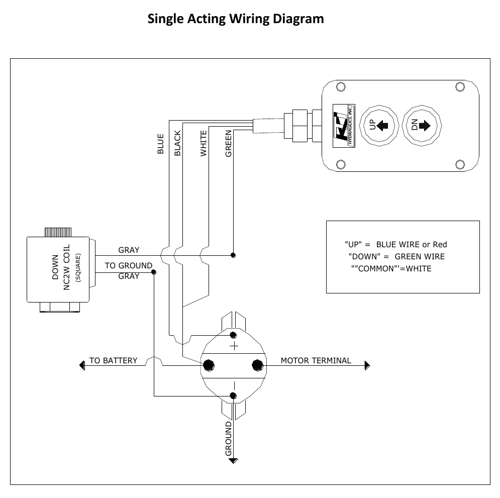
Diagnostic Chart
| Symptom | Check | Spec / Expected | Likely cause & fix |
|---|---|---|---|
| UP is commanded but the motor does not operate. | Confirm the applicable single-acting diagram, then trace the UP signal through its conductor to the starter solenoid and motor; include the common connection in the electrical checks. | In the documented diagram, UP uses blue or red and common uses white; UP supplies the starter solenoid and motor. | A missing command, faulty connection, solenoid fault or motor fault can interrupt powered extension before pump flow is produced. Basis: Hydraulics-Troubleshooting-Manual 2019 |
| The motor runs but the cylinder does not extend. | Trace delivery from the gear pump through the check valve and port P. If pressure testing is needed, use an approved connection and safe test procedure; identify the relief bypass without altering it. | KTI power-up, gravity-down example: 3200 psi, factory preset. | Motor operation does not establish successful hydraulic delivery; inadequate pump output, an obstructed delivery path or bypass flow can prevent extension. Relief bypass at the end of stroke or maximum load is part of the documented operation. Basis: Hydraulics-Troubleshooting-Manual 2019 |
| DOWN is commanded but the cylinder does not retract. | Trace the documented DOWN conductor to the normally closed valve coil, then determine whether the valve opens the return path. Do not treat a stationary pump motor during DOWN as the fault. | DOWN uses green in this diagram and energizes the normally closed two-way valve; lowering does not call for the motor to drive the pump. | A missing coil command or a valve that fails to open can leave the return path closed. Basis: Hydraulics-Troubleshooting-Manual 2019 |
| Retraction speed differs from the operator's expectation. | Determine whether the optional manifold return-flow control is present before evaluating the lowering path; compare operation with the applicable maker's documentation. | An optional manifold flow control can regulate retraction speed; the lesson gives no lowering-speed target. | Return-flow restriction can govern lowering speed, so speed alone does not establish a motor or pump fault. Basis: Hydraulics-Troubleshooting-Manual 2019 |
At the Bay: Diagnose the Case
CASE 1 / 4
UP is commanded but the motor does not operate.
- Test
- Compare
- Correct
Select the next check
Basis: Hydraulics-Troubleshooting-Manual 2019. A likely cause is a hypothesis; confirm it with the applicable service procedure before repair.
Common Bay Mistakes
- ✕ Expecting the pump motor to run during documented gravity lowering.
- ✕ Treating the diagram's wire colors as a universal convention.
- ✕ Adjusting the relief or disturbing its safety wire to repair poor lifting.
- ✕ Opening hydraulic lines before supporting the load and depressurizing.
Quick Check
Practice only — not scored.
Plan the Service Sequence
Planning practice only. Follow the applicable manufacturer's instructions, employer safety program and qualified supervision on real equipment.
Plan the first action. Compare the service steps with the bay mistakes.
Hands-on: Shop Test Equipment
Hydraulic Pressure & Relief Gauge
0–5,000 psi gauge on the pump pressure port, DC clamp meter, battery voltmeter
🛠 Equip your bay for this test →Symptom: Routine check before a customer pickup.
Spec limits used
- 3,200 psi — Primary relief (factory preset) (KTI Hydraulics Troubleshooting Manual 2019)
- 1,500 psi — Secondary relief, circuit 111 (KTI Hydraulics Troubleshooting Manual 2019)
- below 9 V — Low-voltage alarm (KTI remote)
- illustrative only — Motor current & voltage drop (General shop practice)
Simulated readings for practice. Always follow the manufacturer's procedure and values on a real trailer.
Source: Hydraulics-Troubleshooting-Manual 2019 — 5-8