Trace a Power-Up, Power-Down Circuit
- Trace pressure and return flow during extension and powered retraction.
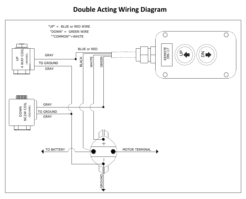
- Distinguish the round UP coil from the square DOWN coil.
- Explain pilot opening and relief protection without altering factory settings.
- Digital multimeter — Check command voltage and ground paths at the starter solenoid and valve coils using the wiring diagram.
- Hydraulic pressure gauge with rated hoses and adapters — Check pressure at manufacturer-approved test points using the equipment-specific procedure; depressurize before connecting or removing test equipment.
- Inspection light — Read port markings and identify coil locations, connectors and hose routing.
- Combination wrenches — Install approved diagnostic adapters only after the load is secured and hydraulic pressure is relieved.
- Rated mechanical supports — Secure the raised trailer structure against movement before inspection or service; do not rely on hydraulic holding alone.
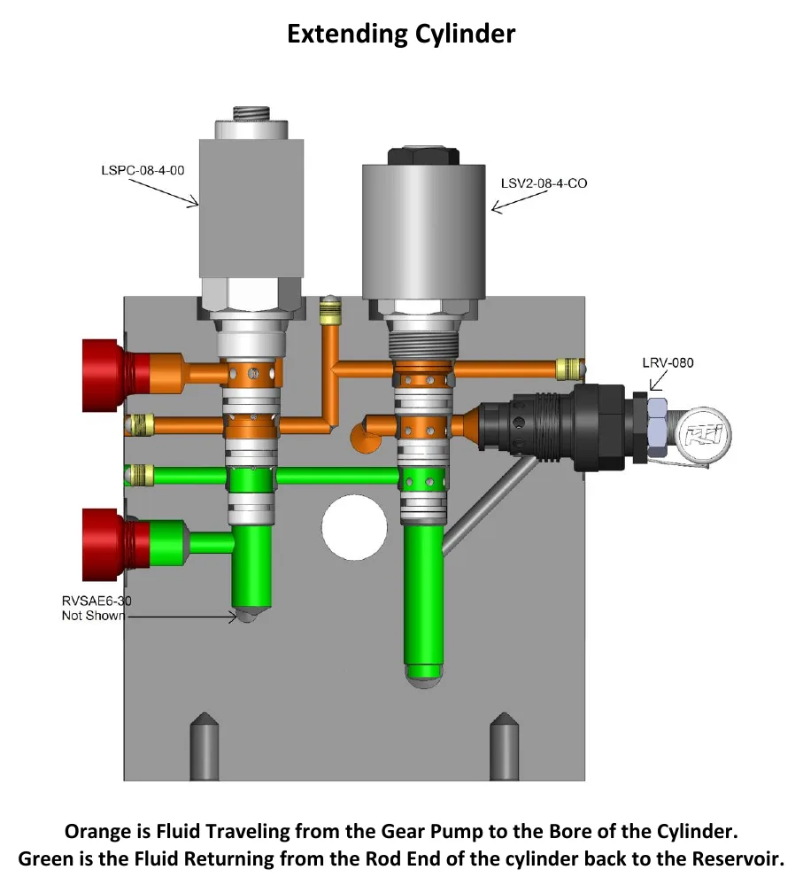
In the documented double-acting arrangement, UP powers the starter solenoid, motor and round directional-valve coil together. The shifted directional valve routes flow through the load-holding valve and out manifold port A to extend the cylinder.
Extension pressure also pilots open the return section of the lowering valve so fluid from the rod end can return to the reservoir. KTI specifies a 2.5:1 pilot ratio and a 3200 psi primary relief setting for this example; values vary by maker.
DOWN powers the starter solenoid, motor and square load-holding-valve coil. Pump flow passes through the directional valve and the lower section of the load-holding valve, then leaves port B to retract the cylinder.
The energized square coil opens the normally closed section of the lowering valve. Bore-end fluid can then return through the directional valve to the reservoir. This is different from assuming that one directional-valve coil alone controls every part of the return path.
At the end of retraction, the secondary relief provides a bypass path. KTI lists 1500 psi for this example and associates the secondary relief with protection against rod-end overpressure and thermal expansion; values vary by maker. The wiring diagram distinguishes the round UP coil from the square DOWN coil.
How It Works
UP: pressure flow and pilot-opened return
In the documented arrangement, UP energizes the starter solenoid, motor and round directional-valve coil together, routing pump flow through the load-holding valve and port A toward the cylinder bore. Extension pressure also pilots open the return section of the lowering valve so rod-end fluid can reach the reservoir; a blocked return path can prevent motion even when pressure reaches the cylinder. KTI specifies a 2.5:1 pilot ratio and a 3200 psi primary relief setting for this example, not as universal settings.
DOWN: powered retraction requires an open return path
DOWN energizes the starter solenoid, motor and square load-holding-valve coil, with pump flow passing through the directional valve and lower load-holding-valve section to port B. The square coil opens the normally closed lowering-valve section so bore-end fluid can return through the directional valve to the reservoir. Powered retraction therefore requires both pressure delivery and return-path opening; the round directional-valve coil does not control every return function.
Relief protection and safe diagnosis
At the end of retraction, the secondary relief provides a bypass path; KTI lists 1500 psi for this example and associates this relief with protection against rod-end overpressure and thermal expansion. Trapped oil can develop pressure as it heats, so relief protection matters even when the cylinder is not moving. Values vary by maker: secure the load and depressurize lines before hydraulic service, and never treat factory-set relief values as field-adjustment targets.
Step-by-Step Procedure
0/7 doneDocumented Double-Acting Values — Values Vary by Maker
| Primary relief | KTI example: 3200 psi. |
| Secondary relief | KTI example: 1500 psi. |
| Lowering-valve pilot ratio | KTI example: 2.5:1. |
Figures
Diagnostic Chart
| Symptom | Check | Spec / Expected | Likely cause & fix |
|---|---|---|---|
| The motor runs on UP, but the cylinder does not extend. | Confirm the round directional-valve coil receives the UP command, then trace pressure flow through the load-holding valve and port A and verify the pilot-operated rod-end return path using the manufacturer's procedure. | UP powers the starter solenoid, motor and round coil together. KTI example: lowering-valve pilot ratio 2.5:1; primary relief 3200 psi. Values vary by maker. | Possible loss of round-coil actuation, restricted extension flow or failure of the pilot-opened return section to open. Basis: Hydraulics-Troubleshooting-Manual 2019 |
| The motor runs on DOWN, but powered retraction does not occur. | Confirm the square load-holding-valve coil receives the DOWN command. Trace pump flow to port B and bore-end return flow through the opened lowering-valve section and directional valve. | DOWN powers the starter solenoid, motor and square coil; the square coil opens the normally closed lowering-valve section. | Possible missing square-coil command, a lowering-valve section that remains closed or an obstruction in the pressure or return path. Basis: Hydraulics-Troubleshooting-Manual 2019 |
| Abnormal pressure behavior is reported at the end of retraction. | Locate the secondary relief and its bypass path in the circuit diagram. Use the maker's approved pressure-test procedure rather than adjusting the valve or repeatedly holding the command against the stop. | KTI example: secondary relief 1500 psi; protects against rod-end overpressure and thermal expansion. Values vary by maker. | Possible restricted bypass path or secondary-relief malfunction; the pressure symptom alone does not establish which component failed. Basis: Hydraulics-Troubleshooting-Manual 2019 |
| A valve command is intermittent or changes when the harness moves. | With the structure secured and personnel clear, inspect connectors and grounds and check the circuit under commanded load. Isolate electrical power before connector repair. | Use equipment-specific electrical test criteria; no electrical acceptance value is supplied in this lesson. | Loose terminals, corrosion or damaged conductors can interrupt coil current even when an unloaded voltage check appears normal. Basis: General shop practice |
At the Bay: Diagnose the Case
CASE 1 / 4
The motor runs on UP, but the cylinder does not extend.
- Test
- Compare
- Correct
Select the next check
Basis: Hydraulics-Troubleshooting-Manual 2019. A likely cause is a hypothesis; confirm it with the applicable service procedure before repair.
Common Bay Mistakes
- ✕ Assuming a running motor proves the required valve coil is energized.
- ✕ Treating the round UP coil as the controller of every return path.
- ✕ Applying KTI example relief values to other makers or adjusting factory settings.
- ✕ Opening a hydraulic connection before securing the load and relieving trapped pressure.
Quick Check
Practice only — not scored.
Plan the Service Sequence
Planning practice only. Follow the applicable manufacturer's instructions, employer safety program and qualified supervision on real equipment.
Plan the first action. Compare the service steps with the bay mistakes.
Hands-on: Shop Test Equipment
Hydraulic Pressure & Relief Gauge
0–5,000 psi gauge on the pump pressure port, DC clamp meter, battery voltmeter
🛠 Equip your bay for this test →Symptom: Routine check before a customer pickup.
Spec limits used
- 3,200 psi — Primary relief (factory preset) (KTI Hydraulics Troubleshooting Manual 2019)
- 1,500 psi — Secondary relief, circuit 111 (KTI Hydraulics Troubleshooting Manual 2019)
- below 9 V — Low-voltage alarm (KTI remote)
- illustrative only — Motor current & voltage drop (General shop practice)
Simulated readings for practice. Always follow the manufacturer's procedure and values on a real trailer.
Source: Hydraulics-Troubleshooting-Manual 2019 — 9-12