Safe, Electrical-First Diagnosis
- Trace electrical commands to the expected hydraulic action.
- Establish hydraulic safety before service.
- Evaluate electrical supply and grounding before blaming hydraulic components.
- Digital multimeter — Check charging and measure starter-solenoid voltage during attempted operation.
- Jumper cable — Perform the documented battery-negative-to-aluminum-manifold ground check while keeping clamps clear of positive terminals and moving parts.
- Insulated hand tools — Service electrical connections after isolating the electrical supply.
- Wire brush — Remove corrosion from disconnected cable terminals and grounding contact surfaces.
- Inspection light — Inspect cable routing, connection condition and the auxiliary-battery charging circuit.
Begin by understanding how the electrical command produces the hydraulic action. The troubleshooting guide emphasizes circuit sequence and identifies electrical faults, especially poor grounding, as common causes of mobile power-unit problems.
Depressurize hydraulic lines before working on the hydraulic system. Fluid injection can initially feel like a small sting but can cause severe injury; the source directs anyone with an injection injury to seek emergency-room treatment immediately.
Low voltage is associated with higher current draw, increased heat and reduced motor speed. The guide links this condition to damaged starter-solenoid contacts, failed valve coils and damaged motor windings. A poor ground can imitate a discharged battery.
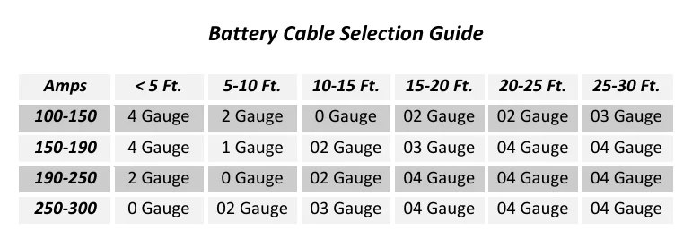
Evaluate battery charging, cable sizing, loose connections, corrosion and the auxiliary-battery charge-wire fuse. The guide describes connecting a jumper cable between battery negative and the aluminum manifold as a quick ground-condition check. Its cable-selection table uses both current and cable length, rather than one universal cable size.
When a cylinder will not extend, check voltage at the starter solenoid while attempting operation. KTI notes that the reading may be below 9.5 volts; this is a diagnostic observation, not a universal operating specification, and values vary by maker. Relief-valve adjustment is not the recommended response to weak performance.
How It Works
Follow the command before condemning the component
Identify how the electrical command activates the motor and valves to produce the requested cylinder movement. An interrupted command or poor ground can prevent hydraulic action even when the hydraulic components are serviceable, so electrical checks come before hydraulic troubleshooting.
Supply quality affects hydraulic performance
The guide associates low voltage with higher current draw, increased heat and reduced motor speed, and links this condition to damaged starter-solenoid contacts, failed valve coils and damaged motor windings. Resistance at loose or corroded connections can reduce the voltage available during operation, while a poor ground can imitate a discharged battery. Cable selection must account for both current and cable length rather than assuming a universal cable size.
Stored pressure remains a service hazard
Depressurize hydraulic lines before hydraulic service; a stopped motor does not by itself establish that pressure has been released. Never use a hand to search for a pressurized leak, because escaping fluid can penetrate skin and initially feel like a small sting. Seek emergency-room treatment immediately for suspected hydraulic injection, and do not adjust factory-set relief valves without consulting the factory.
Step-by-Step Procedure
0/7 doneSource-Specific Diagnostic Observation — Values Vary by Maker
| Voltage during an unsuccessful extension attempt | KTI notes that starter-solenoid voltage may be below 9.5 V; this is not stated as a universal minimum. |
Figures
Diagnostic Chart
| Symptom | Check | Spec / Expected | Likely cause & fix |
|---|---|---|---|
| Cylinder will not extend during an operating command. | Identify the expected operating sequence and measure voltage at the starter solenoid while attempting operation. | KTI notes that starter-solenoid voltage may be below 9.5 V; this is not stated as a universal minimum. | An electrical supply problem may prevent the motor from producing the expected hydraulic action. Basis: Hydraulics-Troubleshooting-Manual 2019 |
| Power unit behaves as though the battery is discharged. | Inspect ground connections and perform the documented jumper-cable check between battery negative and the aluminum manifold. Observe whether operation improves. | Use the documented battery-negative-to-manifold jumper check when evaluating a poor ground. | A poor ground can imitate a discharged battery; improvement with the jumper supports further inspection of the normal ground path. Basis: Hydraulics-Troubleshooting-Manual 2019 |
| Battery supply is inadequate or weak performance returns after charging. | Check whether the battery is being charged and inspect the auxiliary-battery charge-wire fuse or circuit breaker. | Evaluate battery charging and the auxiliary-battery charge-wire protection before proceeding to hydraulic troubleshooting. | An interrupted charging path can leave the battery unable to support operation. Basis: Hydraulics-Troubleshooting-Manual 2019 |
| Motor runs slowly, connections heat up or hydraulic performance is weak. | Inspect for loose connections and corrosion, then compare cable sizing with the source cable-selection table using current and cable length. | The source cable-selection table uses both current and cable length; relief-valve adjustment is not the recommended response to weak performance. | Connection resistance or unsuitable cable sizing can contribute to low voltage and heat under load. Basis: Hydraulics-Troubleshooting-Manual 2019 |
At the Bay: Diagnose the Case
CASE 1 / 4
Cylinder will not extend during an operating command.
- Test
- Compare
- Correct
Select the next check
Basis: Hydraulics-Troubleshooting-Manual 2019. A likely cause is a hypothesis; confirm it with the applicable service procedure before repair.
Common Bay Mistakes
- ✕ Treating a stopped motor as proof that hydraulic pressure is released.
- ✕ Dismissing a suspected injection injury because it feels minor.
- ✕ Treating the KTI voltage observation as a universal operating limit.
- ✕ Adjusting relief pressure before ruling out electrical faults.
Quick Check
Practice only — not scored.
Plan the Service Sequence
Planning practice only. Follow the applicable manufacturer's instructions, employer safety program and qualified supervision on real equipment.
Plan the first action. Compare the service steps with the bay mistakes.
Hands-on: Shop Test Equipment
Hydraulic Pressure & Relief Gauge
0–5,000 psi gauge on the pump pressure port, DC clamp meter, battery voltmeter
🛠 Equip your bay for this test →Symptom: Routine check before a customer pickup.
Spec limits used
- 3,200 psi — Primary relief (factory preset) (KTI Hydraulics Troubleshooting Manual 2019)
- 1,500 psi — Secondary relief, circuit 111 (KTI Hydraulics Troubleshooting Manual 2019)
- below 9 V — Low-voltage alarm (KTI remote)
- illustrative only — Motor current & voltage drop (General shop practice)
Simulated readings for practice. Always follow the manufacturer's procedure and values on a real trailer.
Source: Hydraulics-Troubleshooting-Manual 2019 — 5-22