Isolate Electric Brake Circuit Faults
- Distinguish controller, wiring, connection, and magnet faults.
- Measure magnet voltage and system current safely.
- Isolate excessive current and restore sealed wiring.
- Digital multimeter — Measure voltage across magnet leads and observe changes during controller operation.
- Suitably rated ammeter — Measure current in series with the controller output after checking capacity and polarity; never connect an ammeter directly across the supply.
- DC current clamp — Measure brake-circuit current using an appropriate inductive pickup method without opening the circuit.
- Wire stripper and crimping tool — Prepare and reconnect disturbed magnet wiring with suitable sealed connections.
- Wire brush — Remove connection corrosion as part of a repair that also corrects the source of corrosion.
Electrical troubleshooting begins at the controller, using its manufacturer's adjustment and testing instructions. Loose or corroded connections increase resistance and reduce the voltage available at the magnets, so cleaning a connection must be accompanied by correcting its corrosion problem.
Measure voltage across the magnet leads with the tow vehicle engine running so a low battery does not distort the reading. Observe the voltage increase as the controller is operated; an abrupt high output can explain harsh engagement.
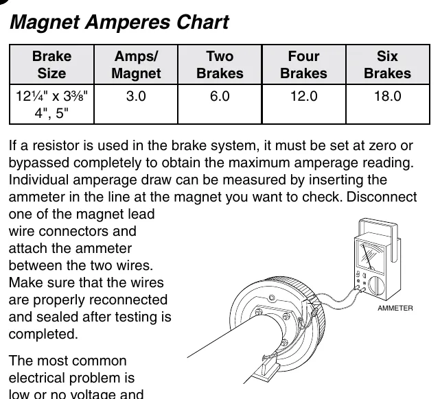
Measure system current with all magnets energized, using a suitably rated ammeter in series with the controller output, or the described inductive pickup method. Current changes with voltage, and a system resistor must be at zero or bypassed for a maximum-current reading. Dexter lists 3.0 A per magnet and 12.0 A for four brakes in the chart on page 23; values vary by maker and brake application.
Low current or voltage can result from poor connections, open or broken wiring, insufficient wire size, or controller and resistor problems. Abnormally high current suggests a short; if unplugging the trailer removes the high reading, the fault is in the trailer, and if it remains high with all magnets disconnected, the fault is in the trailer wiring.
How It Works
Controller output and brake engagement
Begin with the controller manufacturer's adjustment and testing instructions, then measure voltage across the magnet leads with the tow vehicle engine running. During slow controller-bar actuation, the listed behavior is: Starts at 0 V and gradually rises to about 12 V. An abrupt high output can produce harsh engagement because magnet force rises suddenly rather than progressively.
Resistance, voltage, and current
Loose or corroded connections add resistance, reducing voltage available to the magnets and limiting current. Current changes with applied voltage, so a low-current reading cannot identify a failed magnet without checking the supply and circuit conditions. Cleaning a connection without correcting its corrosion problem leaves the mechanism of failure in place.
Reference readings and sectional isolation
For maximum-current testing, energize all magnets and place the system resistor at zero or bypass it under the applicable testing instructions. Dexter lists 3.0 A per magnet and 12.0 A for four brakes, but these references are not universal across makers and applications. Sectional disconnection locates excessive current by showing whether the abnormal reading follows the trailer, remains in its wiring, or disappears when magnet loads are removed.
Step-by-Step Procedure
0/7 doneDexter electric-brake reference values; values vary by maker and application
| Voltage during slow controller-bar actuation | Starts at 0 V and gradually rises to about 12 V |
| Listed magnet current | 3.0 A per magnet |
| Listed four-brake system current | 12.0 A |
Figures
Diagnostic Chart
| Symptom | Check | Spec / Expected | Likely cause & fix |
|---|---|---|---|
| Brakes engage harshly as the controller is operated. | Follow the controller manufacturer's testing instructions. With the engine running and trailer connected, measure across the magnet leads while slowly operating the controller bar. | Starts at 0 V and gradually rises to about 12 V | Abrupt high controller output can explain harsh engagement. Basis: 9-15k complete service manual |
| Magnet voltage is low or braking is weak. | Measure across the magnet leads with the engine running. Inspect connections and wiring, and check controller and resistor operation before condemning magnets. | Use the controller manufacturer's adjustment and testing instructions; listed voltage behavior is: Starts at 0 V and gradually rises to about 12 V. | Poor connections, open or broken wiring, insufficient wire size, or controller and resistor problems can reduce available voltage or current. Basis: 9-15k complete service manual |
| System current is below the applicable brake-chart value. | Confirm meter capacity and polarity, energize all magnets, and verify applied voltage. For maximum current, ensure the system resistor is at zero or bypassed; compare system and individual-magnet readings with the applicable chart. | Dexter reference: 3.0 A per magnet; 12.0 A for four brakes. Values vary by maker and brake application. | Insufficient voltage, excessive connection resistance, an open circuit, or controller and resistor problems may limit current; individual testing helps locate the affected branch. Basis: 9-15k complete service manual |
| Current is abnormally high. | Unplug the trailer and observe whether the high reading disappears. If the fault follows the trailer, disconnect all magnets and test whether excessive current remains in the trailer wiring; reconnect and seal disturbed wiring afterward. | High current disappearing with the trailer unplugged locates the fault in the trailer; high current remaining with all magnets disconnected locates it in trailer wiring. | An electrical short provides an unintended current path. A reading that falls when magnets are disconnected requires further branch or individual-magnet isolation rather than immediate replacement of every magnet. Basis: 9-15k complete service manual |
At the Bay: Diagnose the Case
CASE 1 / 4
Brakes engage harshly as the controller is operated.
- Test
- Compare
- Correct
Select the next check
Basis: 9-15k complete service manual. A likely cause is a hypothesis; confirm it with the applicable service procedure before repair.
Common Bay Mistakes
- ✕ Treating Dexter reference currents as universal specifications.
- ✕ Condemning a magnet from low current without checking voltage.
- ✕ Using an underrated ammeter or incorrect polarity.
- ✕ Cleaning corrosion without correcting its cause or resealing wiring.
Quick Check
Practice only — not scored.
Plan the Service Sequence
Planning practice only. Follow the applicable manufacturer's instructions, employer safety program and qualified supervision on real equipment.
Plan the first action. Compare the service steps with the bay mistakes.
Source: 9-15k complete service manual — 22-24