Find Why Alignment Will Not Stay Correct
- Separate measurement setup errors from actual axle misalignment.
- Distinguish lateral position, front thrust, and rear scrub alignment.
- Find and correct suspension faults that prevent alignment retention.
- Wheel chocks — Secure the trailer against unintended movement while service and parking brakes are released for measurement.
- Tape measure — Compare alignment distances using consistent tape tension and specified axle references.
- Spirit level — Check that the trailer is level in both directions before taking measurements.
- Torque wrench and suitable sockets — Tighten adjustable-track-arm clamps to the applicable manufacturer's specification before remeasuring.
- Inspection light — Inspect track-arm bushings, clamp areas, adjusting threads, and spring leaves for wear or damage.
Excessive tire wear, off-tracking, and hard pulling can lead to an alignment inspection. For the covered adjustable-track-arm suspension, unload the trailer, release suspension binds, and level the trailer in both directions before measuring.
Measure with service and parking brakes released and with the kingpin or coupler at the correct height. Use axle-end extenders or unobstructed axle-center references rather than rims, hubcaps, drums, or suspension brackets.
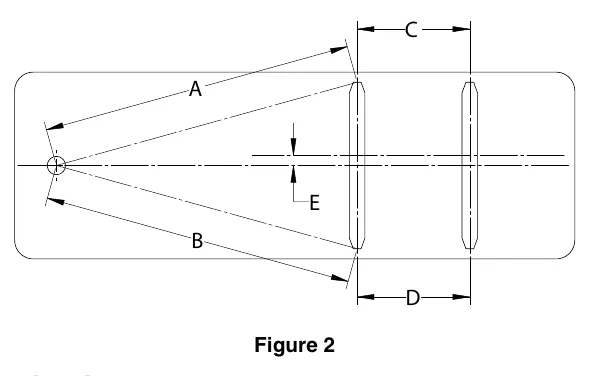
The measurement sequence separates lateral position, front-axle thrust alignment, and rear-axle scrub alignment. Align the front axle to the kingpin or coupler, then align succeeding axles to the front axle. Dexter specifies that the covered rear-axle spacing measurements agree within 1/16 inch; values vary by maker and suspension procedure.
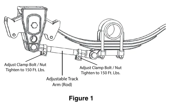
A successful adjustment can be lost if the supporting hardware is worn or loose. Track-arm slack indicates wear in bushings or arm parts, and loose clamps wear the adjusting threads so alignment cannot be retained. Recheck measurements after tightening, and replace broken spring leaves before they overload the remaining leaves.
How It Works
Establish a trustworthy measurement setup
For the covered adjustable-track-arm suspension, unload the trailer, release suspension binds using the source's backward-and-forward preparation, level the trailer in both directions, and set the kingpin or coupler to the correct height. Secure the trailer against unintended movement and release service and parking brakes before measuring; bind and brake restraint can hold the suspension in a position that changes when those forces are removed. Use axle-end extenders or unobstructed axle-center references with consistent tape tension, not rims, hubcaps, brake drums, or suspension brackets.
Separate the alignment relationships
Check lateral position before aligning the front axle to the kingpin or coupler, then align succeeding axles to the front axle. For the covered Dexter procedure, lateral centerline offset is 1/4 inch or less, front thrust measurements A and B are Equal within 1/8 inch or 0.1 degree, and rear spacing measurements C and D are Equal within 1/16 inch. These limits apply to the covered suspension and procedure rather than every trailer; thrust error can steer the trailer away from its intended path, while axle-to-axle disagreement promotes tire scrub.
Alignment must remain mechanically secure
Track-arm slack indicates wear in bushings or arm parts, allowing axle position to change under load even when a static measurement appears correct. Loose clamps permit movement that wears adjusting threads, so tightening alone must not be assumed to restore damaged components. Correct worn or loose components, replace broken spring leaves before they overload the remaining leaves, and recheck alignment after tightening the clamps to the applicable specification.
Step-by-Step Procedure
0/7 doneDexter covered heavy-duty suspension limits; values vary by maker and procedure
| Lateral centerline offset | 1/4 inch or less |
| Front thrust measurements A and B | Equal within 1/8 inch or 0.1 degree |
| Rear spacing measurements C and D | Equal within 1/16 inch |
Figures
Diagnostic Chart
| Symptom | Check | Spec / Expected | Likely cause & fix |
|---|---|---|---|
| Measurements change between attempts without an intentional adjustment. | Verify the trailer is unloaded, suspension binds are released, the trailer is level in both directions, and coupling height is correct. Confirm brakes are released, references are axle-based, and tape tension is consistent. | Use axle-end extenders or unobstructed axle-center references; do not substitute rims, hubcaps, drums, or suspension brackets. | Suspension bind, brake restraint, incorrect setup, or inconsistent reference selection can mimic changing alignment. Basis: 9-15k complete service manual |
| Off-tracking or hard pulling prompts an alignment inspection. | After validating setup, check lateral position and compare front thrust measurements A and B from the specified kingpin or coupler reference. | Covered Dexter lateral centerline offset: 1/4 inch or less. Front thrust measurements A and B: Equal within 1/8 inch or 0.1 degree. | Incorrect lateral position or front-axle thrust alignment may contribute; symptoms alone do not establish the fault. Basis: 9-15k complete service manual |
| Rear tires show scrub-related wear despite acceptable front-axle alignment. | Confirm front-axle alignment, then compare rear spacing measurements C and D using the prescribed axle references. | Covered Dexter rear spacing measurements C and D: Equal within 1/16 inch. | A following axle that is not aligned to the front axle can force its tires to scrub rather than roll along a common path. Basis: 9-15k complete service manual |
| Alignment appears correct after adjustment but will not stay correct. | Inspect track-arm slack, bushings, arm parts, clamp security, adjusting-thread damage, and broken spring leaves. Correct defects, tighten clamps to the applicable specification, and remeasure. | Use the applicable clamp-tightening specification; the lesson provides no clamp torque value. Replace broken spring leaves and recheck measurements after tightening. | Worn supporting parts allow axle movement, loose clamps wear adjusting threads, and broken leaves overload the remaining leaves. Basis: 9-15k complete service manual |
At the Bay: Diagnose the Case
CASE 1 / 4
Measurements change between attempts without an intentional adjustment.
- Test
- Compare
- Correct
Select the next check
Basis: 9-15k complete service manual. A likely cause is a hypothesis; confirm it with the applicable service procedure before repair.
Common Bay Mistakes
- ✕ Adjusting axles before eliminating suspension bind and setup errors.
- ✕ Using convenient wheel or brake surfaces instead of specified axle references.
- ✕ Applying covered Dexter limits to an unrelated suspension procedure.
- ✕ Treating clamp tightening as a cure for worn threads or track-arm slack.
Quick Check
Practice only — not scored.
Plan the Service Sequence
Planning practice only. Follow the applicable manufacturer's instructions, employer safety program and qualified supervision on real equipment.
Plan the first action. Compare the service steps with the bay mistakes.
Source: 9-15k complete service manual — 71-74