Diagnose Air Brake Force and Release Problems
- Trace braking force from air supply to lining contact.
- Evaluate chamber stroke, linkage geometry, and brake release.
- Distinguish adjustment problems from underlying component faults.
- Wheel chocks — Secure the vehicle against movement before checking brake application or release.
- Rated jack and support stands — Lift and securely support the trailer when access or wheel movement is required; never rely on the jack alone.
- Ruler or tape measure — Measure pushrod travel at the clevis pin from the released position to the applied position.
- Angle gauge — Check the applied angle between the pushrod and slack adjuster.
- Feeler gauge set — Check lining-to-drum contact with the brakes applied, using the specified blade.
- Inspection light — Inspect mounting, return springs, linkage movement, and accessible foundation-brake components.
The air chamber changes compressed-air pressure into pushrod force. The slack adjuster converts that force into camshaft torque, and the S-cam spreads the shoes against the drum. Wrong chamber size or slack-adjuster length can therefore affect braking even when air is available.
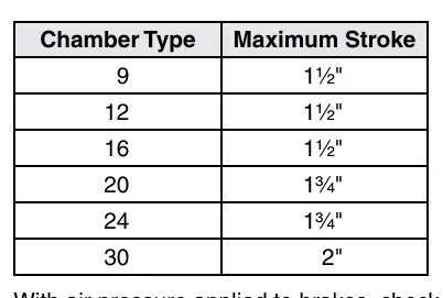
Stroke and contact checks evaluate the force path under application. Compare pushrod travel with the chamber-specific limit, check lining contact with the drum, and confirm that the brakes return to their relaxed position after pressure is released. Dexter lists a 2-inch maximum stroke for a type 30 chamber; limits vary by maker and chamber.
Overheating can involve weak or broken return springs, bearing adjustment, sticky air-system valves, incorrect chamber or slack-adjuster mounting, and frozen camshafts or shoes. Repeated adjustment alone does not address these listed causes.
Installation direction also matters: camshaft rotation opposite to wheel rotation can produce noise, chatter, and wheel hop. A broken return spring requires investigation of the reason for breakage as well as replacement, and air-system malfunctions require the system manufacturer's troubleshooting instructions.
How It Works
Follow the complete force path
The air chamber converts compressed-air pressure into pushrod force, the slack adjuster converts that force into camshaft torque, and the S-cam spreads the shoes against the drum. Chamber size, slack-adjuster length, and linkage geometry determine how effectively that force reaches the friction surfaces, so available air alone does not prove correct braking.
Evaluate application and release separately
Applied pushrod travel, pushrod-to-slack-adjuster angle, and lining contact reveal different parts of the force path; compare each with the applicable chamber and brake requirements. After pressure is released, confirm that every brake returns to its relaxed position, because continued lining contact generates frictional heat and accelerates wear.
Find the cause before repeating an adjustment
Overheating can result from weak or broken return springs, bearing adjustment, sticky valves, incorrect mounting, or frozen camshafts or shoes; repeated adjustment does not correct these faults. Investigate why a return spring broke, check camshaft rotation when chatter or wheel hop suggests an installation problem, and use the system manufacturer's instructions for air-system malfunctions. Have a qualified mechanic assess the complete tow vehicle and trailer system, and do not disassemble a spring-brake chamber: its compressed spring is hazardous, and caging and servicing are for qualified personnel.
Step-by-Step Procedure
0/7 doneDexter air-brake checks; values vary by maker and application
| Type 30 chamber maximum stroke | 2 inches |
| Applied pushrod-to-slack-adjuster angle | Approximately 90 degrees, plus or minus 5 degrees |
| Applied lining-contact check | A 0.010-inch feeler gauge should not fit between lining and drum |
Figures
Diagnostic Chart
| Symptom | Check | Spec / Expected | Likely cause & fix |
|---|---|---|---|
| Weak braking despite available air | Verify chamber size, slack-adjuster length, and mounting against the application; measure applied pushrod travel at the clevis pin and check the applied linkage angle. | Type 30 chamber maximum stroke: 2 inches. Applied pushrod-to-slack-adjuster angle: Approximately 90 degrees, plus or minus 5 degrees. Confirm applicability because limits vary by maker and chamber. | An incorrect chamber, incorrect lever length, poor mounting geometry, or excessive travel can compromise force delivery even when air is available. Basis: 9-15k complete service manual |
| Chamber movement occurs, but lining contact is questionable | With the brakes applied, check lining-to-drum contact rather than treating visible pushrod movement as proof of effective braking. | A 0.010-inch feeler gauge should not fit between lining and drum | Poor lining contact prevents the foundation brake from using the available application force effectively. Basis: 9-15k complete service manual |
| Brake remains applied or overheats after release | Release pressure and confirm normal return of every brake. Investigate return springs, bearing adjustment, valves, mounting, and frozen camshafts or shoes; follow the air-system manufacturer's troubleshooting instructions for suspected air faults. | Every brake must return to its relaxed position after pressure is released. | Weak or broken springs, sticky valves, incorrect mounting, or seized components can prevent release; bearing adjustment can also contribute to overheating. Basis: 9-15k complete service manual |
| Noise, chatter, or wheel hop suggests an installation problem | Check camshaft rotation direction relative to wheel rotation and investigate installation direction before assuming adjustment is the remedy. | Camshaft rotation opposite to wheel rotation can produce noise, chatter, and wheel hop. | Incorrect installation direction can create the listed operating symptoms. Basis: 9-15k complete service manual |
At the Bay: Diagnose the Case
CASE 1 / 4
Weak braking despite available air
- Test
- Compare
- Correct
Select the next check
Basis: 9-15k complete service manual. A likely cause is a hypothesis; confirm it with the applicable service procedure before repair.
Common Bay Mistakes
- ✕ Applying a chamber-specific stroke limit to every chamber.
- ✕ Assuming available air proves correct braking force.
- ✕ Repeatedly adjusting a hot brake without diagnosing release faults.
- ✕ Disassembling a spring-brake chamber or attempting unqualified caging.
Quick Check
Practice only — not scored.
Plan the Service Sequence
Planning practice only. Follow the applicable manufacturer's instructions, employer safety program and qualified supervision on real equipment.
Plan the first action. Compare the service steps with the bay mistakes.
Source: 9-15k complete service manual — 43-55