Replace Clip-On Pads and Protect Slider Seals
- Install clip-on pads using the kit-specific retention method.
- Identify slider, bore, seal, and caliper defects before reassembly.
- Protect O-rings and verify brake readiness before operation.
- Socket and wrench set — Remove slider-bolt nuts and install new locknuts with correctly fitting tools.
- Torque wrench — Tighten slider-bolt locknuts to the applicable kit specification.
- Caliper support hook — Support the removed caliper without placing its weight on the hydraulic hose.
- Inspection light — Illuminate slider surfaces, yoke bores, O-rings, dust boots, and possible fluid leaks.
- Brake piston retraction tool — Retract pistons sufficiently for reassembly without damaging surrounding components.
This kit procedure starts with the tire-wheel assembly removed and the hydraulic system unpressurized. Remove the slider-bolt nuts and withdraw the bolts, then lift the caliper from the yoke without hanging it from the hose. Discard the old pads and any old anti-rattle springs; those springs are not required with this kit.
Inspect the slider bolts for straightness, rust pits, missing chrome, and cracks in their chrome plating. Check anchor-yoke bores for corrosion and excessive wear, and inspect O-rings for cuts or nicks. The caliper must be free of fluid leaks and deteriorated or torn dust boots and O-rings; repair or replace unacceptable components as directed.
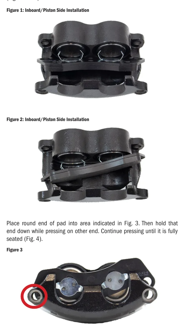
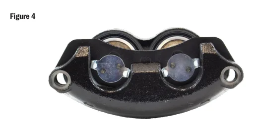
The replacement pads are identical and carry attached retaining clips. Their clips engage the piston bores and caliper casting slots. Seat each pad by placing its rounded end in the indicated area, holding that end down, and pressing the other end until fully seated.
Retract the pistons sufficiently for reassembly and apply a light film of high-temperature brake lubricant to the caliper and yoke O-rings. Insert slider bolts from the outboard side without force or hammering, then secure them with new locknuts. Dexter specifies 15–30 ft-lb for the slider-bolt locknuts in this 10–16K clip-on pad instruction; values vary by maker and document revision. Actuate the brakes repeatedly to remove excess pad clearance before vehicle operation.
How It Works
Clip-on retention is kit-specific
Begin with the tire-wheel assembly removed and the hydraulic system unpressurized; remove the slider-bolt nuts and bolts, then support the caliper without loading its hose. The replacement pads are identical, and their attached clips engage the piston bores and caliper casting slots: hold the rounded end down in the indicated area while pressing the opposite end fully into place. Discard the used pads and old anti-rattle springs for this kit, but do not apply that spring-removal instruction to another retention design.
Free sliding depends on sound surfaces and protected seals
Inspect slider bolts for straightness, rust pits, missing chrome, and cracked chrome plating; check yoke bores for corrosion and excessive wear, and inspect O-rings, dust boots, caliper leakage, and rotor condition. Corrosion and damaged sliding surfaces can resist caliper movement, while damaged boots allow contamination to accelerate wear. Retract the pistons sufficiently, apply a light film of high-temperature brake lubricant to the caliper and yoke O-rings, and insert the bolts from the outboard side without forcing or hammering them.
Fastener security and clearance recovery
Install new slider-bolt locknuts; Dexter specifies 15–30 ft-lb in this 10–16K clip-on pad instruction, and values vary by maker and document revision. Actuate the brakes repeatedly before vehicle operation to remove excess pad clearance created during piston retraction. This restores pad proximity to the rotor rather than leaving the initial brake application to take up the reassembly clearance.
Step-by-Step Procedure
0/7 doneDexter 10–16K clip-on pad instruction values; values vary by maker and revision
| Slider-bolt locknuts | 15–30 ft-lb |
Figures
Diagnostic Chart
| Symptom | Check | Spec / Expected | Likely cause & fix |
|---|---|---|---|
| A replacement pad will not seat securely. | Confirm that the attached clips align with the piston bores and caliper casting slots, and that old anti-rattle springs have been discarded for this kit. Hold the rounded end down while pressing the opposite end into place. | Each pad must be fully seated using its attached retaining clips. | Clip misalignment, incorrect seating technique, or retained old spring hardware may prevent proper seating. Basis: 1016KDiscBrake |
| A slider bolt resists insertion. | Stop rather than hammering. Check bolt straightness and plating, yoke-bore corrosion or wear, O-ring condition, and the light lubricant film; confirm insertion is from the outboard side. | Insert slider bolts without force or hammering; lightly lubricate caliper and yoke O-rings with high-temperature brake lubricant. | Damaged sliding surfaces, corroded bores, or an obstructing O-ring can resist insertion and risk seal damage. Basis: 1016KDiscBrake |
| Fluid leakage or damaged sealing components are found. | Inspect the caliper for leakage and inspect dust boots and O-rings for deterioration, tears, cuts, or nicks. Repair or replace unacceptable components as directed before proceeding. | The caliper must be free of fluid leaks and deteriorated or torn dust boots and O-rings. | Fluid leakage indicates a hydraulic sealing problem; damaged protective boots can admit contamination. Basis: 1016KDiscBrake |
| Reassembly is complete, but brake readiness has not been established. | Confirm new locknuts were installed and tightened to the applicable instruction, then actuate the brakes repeatedly to remove excess pad clearance before operation. | Slider-bolt locknuts: 15–30 ft-lb for this Dexter 10–16K clip-on pad instruction; values vary by maker and revision. | Piston retraction leaves excess pad clearance, and an unverified fastening procedure leaves retention uncertain. Basis: 1016KDiscBrake |
At the Bay: Diagnose the Case
CASE 1 / 4
A replacement pad will not seat securely.
- Test
- Compare
- Correct
Select the next check
Basis: 1016KDiscBrake. A likely cause is a hypothesis; confirm it with the applicable service procedure before repair.
Common Bay Mistakes
- ✕ Hanging the removed caliper from its hydraulic hose.
- ✕ Hammering slider bolts through resistant O-rings.
- ✕ Reusing old locknuts or assuming another document uses the same torque.
- ✕ Applying this kit's spring-discard instruction to another pad-retention design.
Quick Check
Practice only — not scored.
Plan the Service Sequence
Planning practice only. Follow the applicable manufacturer's instructions, employer safety program and qualified supervision on real equipment.
Plan the first action. Compare the service steps with the bay mistakes.
Hands-on: Test Bench Practice
Symptom: Healthy trailer. Learn what good readings look like.
Tap a point to place the red probe.
Good system: ~12.6 V at pins, 3.2 Ω across a 12×2-inch magnet (unplugged), 3.0 A per magnet at 12 V full gain, and at least 10.5 V at the magnet — the chart values from the axle manuals.
Hands-on: Shop Test Equipment
Hydraulic Pressure & Relief Gauge
0–5,000 psi gauge on the pump pressure port, DC clamp meter, battery voltmeter
🛠 Equip your bay for this test →Symptom: Routine check before a customer pickup.
Spec limits used
- 3,200 psi — Primary relief (factory preset) (KTI Hydraulics Troubleshooting Manual 2019)
- 1,500 psi — Secondary relief, circuit 111 (KTI Hydraulics Troubleshooting Manual 2019)
- below 9 V — Low-voltage alarm (KTI remote)
- illustrative only — Motor current & voltage drop (General shop practice)
Simulated readings for practice. Always follow the manufacturer's procedure and values on a real trailer.
Source: 1016KDiscBrake — 1-2