Maintain Caliper Bushings and Complete Wheel Installation
- Investigate rotor grooves without assuming a single failed component.
- Service caliper bushings with compatible lubricant and correct bolt assembly practices.
- Complete wheel installation using the applicable tightening procedure and recheck schedule.
- Inspection light — Illuminate pad areas and both rotor faces to identify grooves and abnormal wear.
- Socket set and ratchet — Remove and reinstall caliper mounting bolts and wheel fasteners with correctly fitting sockets.
- Torque wrench — Apply the applicable caliper-bolt torque and the separately identified wheel-fastener torque.
- Clean shop cloths — Remove accessible residue and keep grease away from pad and rotor friction surfaces.
- Vehicle-rated jack and support stands — Lift and securely support the trailer according to its service instructions before wheel removal.
Periodic pad inspection should include the rotor surfaces. The source identifies deep grooves on either rotor face as a possible indication of a caliper-piston problem, slider-bolt problem, or residual hydraulic pressure. Such grooves are a diagnostic clue, not proof of only one failed component.
Lippert specifies visual disc-pad inspection every 36,000 miles or 12 months, whichever occurs first, for the covered axle manual. That manual also directs rotor turning when pads are replaced. Values and service requirements vary by maker, so this instruction must not be treated as a universal replacement rule.
When the covered caliper mounting bolts have been removed, the source requires blue thread-locking compound during reassembly and lubrication inside the caliper bushings through which the slider bolts pass. Use silicone-based grease for those bushings because their rubber is incompatible with petroleum-based grease. Lippert specifies 40–50 ft-lb for these caliper mounting bolts; values vary by maker.
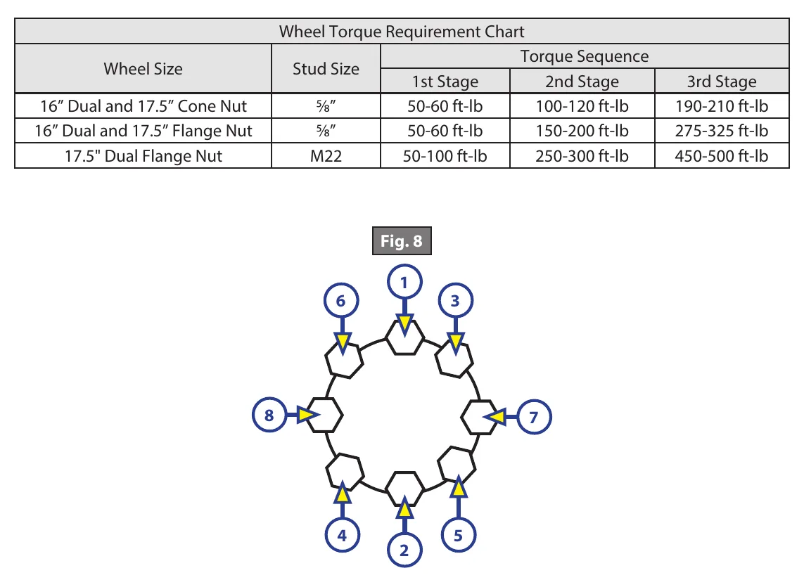
Wheel installation is a separate controlled fastening task. Match fasteners to the wheel seat, start them by hand, and tighten with a torque wrench in the specified sequence and stages. Lippert calls for wheel-fastener rechecks after 10, 25, and 50 miles in this manual; values vary by maker. Use the correct wheel-and-fastener row rather than treating caliper torque as wheel torque.
How It Works
Rotor grooves guide diagnosis
Inspect rotor surfaces during pad inspection: deep grooves on either face can indicate a piston problem, slider-bolt problem, or residual hydraulic pressure, but do not isolate the fault by themselves. Restricted caliper movement or pressure that does not release can keep a pad loaded against the rotor, promoting heat and uneven wear. The covered Lippert manual specifies visual disc-pad inspection every 36,000 miles or 12 months, whichever comes first, and directs rotor turning when pads are replaced; these requirements are not universal.
Bushing compatibility and bolt retention
The covered rubber caliper bushings require silicone-based grease inside the passages through which the slider bolts travel because petroleum-based grease is incompatible with their rubber. Incompatible lubricant can degrade the rubber and interfere with free sliding, preventing the caliper from applying and releasing evenly. When removed caliper mounting bolts are reinstalled, the covered Lippert procedure requires blue thread-locking compound and 40–50 ft-lb; verify applicability rather than transferring these requirements to another assembly.
Wheel fastening is a separate operation
Match each fastener to the wheel seat and start it by hand so seat mismatch or thread resistance is detected before tightening. Use a torque wrench with the specified sequence and stages to develop controlled clamping force; insufficient clamp can allow loosening, while excessive tightening can damage studs. Obtain torque from the correct wheel-and-fastener row rather than the caliper specification, and follow the covered Lippert rechecks after 10, 25, and 50 miles only where that manual applies.
Step-by-Step Procedure
0/7 doneLippert covered disc and wheel-service values; values vary by maker
| Visual disc-pad inspection | 36,000 miles or 12 months, whichever comes first |
| Disc-caliper mounting bolts | 40–50 ft-lb |
| Wheel-fastener recheck distances | 10, 25, and 50 miles |
Figures
Diagnostic Chart
| Symptom | Check | Spec / Expected | Likely cause & fix |
|---|---|---|---|
| Deep grooves appear on either rotor face. | Inspect pads and rotor faces, then investigate piston operation, slider-bolt movement, and possible residual hydraulic pressure before selecting a repair. | Deep grooves are a diagnostic clue, not proof of a single failed component. | Possible caliper-piston problem, slider-bolt problem, or residual hydraulic pressure. Basis: Lippert-Axle-8K-16K-Manual |
| Caliper sliding is restricted and the bushing lubricant is suspect. | Confirm the lubricant used inside the covered bushings and inspect their condition and slider movement. | Use silicone-based grease; petroleum-based grease is incompatible with the covered rubber bushings. | Incompatible lubricant may degrade rubber and interfere with movement; investigate mechanical restriction as well. Basis: Lippert-Axle-8K-16K-Manual |
| Removed caliper mounting bolts are ready for reassembly, but retention requirements are uncertain. | Identify the covered assembly, confirm blue thread-locking compound is applied during reassembly, and tighten with a torque wrench. | Covered Lippert caliper mounting bolts: 40–50 ft-lb, with blue thread-locking compound during reassembly. | Omitted thread-locking compound or an unrelated torque specification can leave the assembly improperly secured. Basis: Lippert-Axle-8K-16K-Manual |
| Wheel-fastener security is uncertain after installation. | Confirm fastener-to-seat compatibility, the correct wheel-and-fastener specification, and completion of the prescribed tightening sequence, stages, and rechecks. | Covered Lippert wheel-fastener rechecks: 10, 25, and 50 miles. Wheel torque must come from the applicable wheel-and-fastener row. | Seat mismatch or incorrect tightening can contribute to wheel loosening or stud failure. Basis: Lippert-Axle-8K-16K-Manual |
At the Bay: Diagnose the Case
CASE 1 / 4
Deep grooves appear on either rotor face.
- Test
- Compare
- Correct
Select the next check
Basis: Lippert-Axle-8K-16K-Manual. A likely cause is a hypothesis; confirm it with the applicable service procedure before repair.
Common Bay Mistakes
- ✕ Treating deep rotor grooves as proof of a seized piston.
- ✕ Using petroleum-based grease in the covered rubber bushings.
- ✕ Applying the covered rotor-turning instruction universally.
- ✕ Using caliper-bolt torque as wheel-fastener torque.
Quick Check
Practice only — not scored.
Plan the Service Sequence
Planning practice only. Follow the applicable manufacturer's instructions, employer safety program and qualified supervision on real equipment.
Plan the first action. Compare the service steps with the bay mistakes.
Hands-on: Test Bench Practice
Symptom: Healthy trailer. Learn what good readings look like.
Tap a point to place the red probe.
Good system: ~12.6 V at pins, 3.2 Ω across a 12×2-inch magnet (unplugged), 3.0 A per magnet at 12 V full gain, and at least 10.5 V at the magnet — the chart values from the axle manuals.
Hands-on: Shop Test Equipment
Hydraulic Pressure & Relief Gauge
0–5,000 psi gauge on the pump pressure port, DC clamp meter, battery voltmeter
🛠 Equip your bay for this test →Symptom: Routine check before a customer pickup.
Spec limits used
- 3,200 psi — Primary relief (factory preset) (KTI Hydraulics Troubleshooting Manual 2019)
- 1,500 psi — Secondary relief, circuit 111 (KTI Hydraulics Troubleshooting Manual 2019)
- below 9 V — Low-voltage alarm (KTI remote)
- illustrative only — Motor current & voltage drop (General shop practice)
Simulated readings for practice. Always follow the manufacturer's procedure and values on a real trailer.
Source: Lippert-Axle-8K-16K-Manual — 9-18