System and Individual Magnet Current
- Select the correct current reference for brake size, brake count, and maker.
- Measure system and individual magnet current safely under documented conditions.
- Locate electrical faults and restore sealed wiring after testing.
- Series ammeter — Measure total brake-output current and individual magnet current after verifying adequate capacity and correct polarity.
- Digital multimeter — Check voltage at the controller, trailer connector, and magnets to localize electrical losses.
- Wire stripper and crimper — Restore disturbed wiring connections where connector replacement is necessary.
- Heat gun — Seal heat-shrink wiring repairs after reconnecting tested circuits.
System amperage represents the current drawn by the energized brake magnets, and it changes with voltage. Measure it with the tow vehicle engine running. Before connecting an ammeter, verify that its capacity is sufficient and observe polarity to avoid instrument damage.
For an in-series system measurement, disconnect the controller's blue brake-output wire and insert the ammeter into that circuit. If a system resistor is present, set it to zero or bypass it completely for the maximum-current reading. Use the controller and equipment instructions rather than interpreting a reduced-output reading as a full-output test.
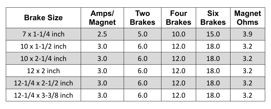
The nominal chart conditions are important: Bostail specifies 12 V, magnets at normal operating temperature rather than cold, a system resistor at zero, and maximum controller gain. For its listed 12 x 2 inch brakes, the chart gives 3.0 A per magnet, 12.0 A for four brakes, and 3.2 ohms per magnet. Values vary by maker and brake size, so select the correct chart row.
To measure an individual magnet, separate one magnet lead connector and place the ammeter between the separated wires. Reconnect and seal the wires when testing is complete. If voltage and amperage are unsatisfactory, move from the controller to the connector and then to individual magnets; Bostail states that 12 V at the controller should provide at least 10.5 V at each magnet, and values vary by maker.
How It Works
Current readings require controlled conditions
System amperage is the combined current drawn by energized magnets, and it changes with applied voltage and magnet resistance. Measure with the tow vehicle engine running, then compare against the applicable maker's chart under its documented conditions. Bostail specifies 12 V, normal operating magnet temperature rather than cold, a system resistor at zero, and maximum controller gain.
Series measurement follows the current path
An ammeter belongs in series so the current being evaluated passes through the instrument; connecting it across a supply can create a short circuit. For system current, disconnect the controller's blue brake-output wire and insert the adequately rated ammeter into that circuit with correct polarity. For individual current, separate one magnet-lead connection and place the meter between the separated wires, then reconnect and seal the wiring afterward.
Separate supply problems from magnet problems
Low total current does not by itself prove failed magnets: reduced controller output, connection resistance, or an interrupted branch can reduce the reading. Follow unsatisfactory voltage and amperage from the controller to the connector and then to individual magnets, because resistance in wiring or connections consumes voltage that should reach the load. For Bostail's listed 12 x 2 inch brakes, the references are 3.0 A per magnet, 12.0 A for four brakes, and 3.2 ohms per magnet; these values must not be applied indiscriminately to other brakes.
Step-by-Step Procedure
0/7 doneBostail diagnostic references; values vary by maker
| Nominal current-chart voltage | 12 V |
| 12 x 2 inch brake, individual magnet | 3.0 A |
| Four 12 x 2 inch brakes | 12.0 A |
| 12 x 2 inch brake magnet resistance | 3.2 ohms |
| Magnet voltage with 12 V controller output | At least 10.5 V |
Figures
Diagnostic Chart
| Symptom | Check | Spec / Expected | Likely cause & fix |
|---|---|---|---|
| Total current is below the selected chart reference. | Confirm brake size and count, run the tow vehicle engine, and verify chart voltage, magnet temperature, maximum controller gain, and the system resistor setting before condemning components. | Bostail lists 12.0 A for four 12 x 2 inch brakes at 12 V with magnets at normal operating temperature, the system resistor at zero, and maximum controller gain. | Reduced test output, incorrect chart selection, or an actual circuit fault can produce a low reading. Basis: Bostail 8K Axle Manual |
| Controller voltage is satisfactory but magnet voltage is low. | Measure from the controller to the connector and then to each magnet to identify where voltage is being lost. | Bostail states that 12 V at the controller should provide at least 10.5 V at each magnet; values vary by maker. | Excess resistance in wiring, connectors, or the return path can reduce voltage available at the magnet. Basis: Bostail 8K Axle Manual |
| An individual magnet draws less current than its applicable reference. | Separate one magnet-lead connection and measure in series with a suitably rated ammeter. Verify voltage and documented temperature conditions before interpreting the result; reconnect and seal the connection afterward. | For Bostail's listed 12 x 2 inch brakes: 3.0 A per magnet and 3.2 ohms per magnet under the applicable documented conditions. | Insufficient supply voltage, connection resistance, or a damaged magnet circuit may reduce current. Basis: Bostail 8K Axle Manual |
| Ammeter shows no current even though the circuit previously operated. | De-energize before changing connections. Check meter lead placement, current-function selection, the meter fuse where fitted, and continuity of the series test connection. | Use an intact, correctly configured meter rated for the circuit; follow its operating instructions. | An open meter fuse, incorrect input jack, or incomplete series connection can interrupt the circuit and imitate a trailer fault. Basis: General shop practice |
At the Bay: Diagnose the Case
CASE 1 / 4
Total current is below the selected chart reference.
- Test
- Compare
- Correct
Select the next check
Basis: Bostail 8K Axle Manual. A likely cause is a hypothesis; confirm it with the applicable service procedure before repair.
Common Bay Mistakes
- ✕ Never connect an ammeter across the supply as though measuring voltage.
- ✕ Do not interpret reduced controller output as a maximum-current test.
- ✕ Do not compare cold magnets or another brake size against the listed chart conditions.
- ✕ Do not leave tested magnet connections loose or unsealed.
Quick Check
Practice only — not scored.
Plan the Service Sequence
Planning practice only. Follow the applicable manufacturer's instructions, employer safety program and qualified supervision on real equipment.
Plan the first action. Compare the service steps with the bay mistakes.
Hands-on: Test Bench Practice
Symptom: Healthy trailer. Learn what good readings look like.
Tap a point to place the red probe.
Good system: ~12.6 V at pins, 3.2 Ω across a 12×2-inch magnet (unplugged), 3.0 A per magnet at 12 V full gain, and at least 10.5 V at the magnet — the chart values from the axle manuals.
Hands-on: Shop Test Equipment
IPA #9107B Electric Brake Force Meter
Plugs into the truck's 7-way socket on a 25 ft cable; simulates a trailer load and shows controller output on 10 blue LEDs
🛠 Equip your bay for this test →Symptom: Customer wants the truck checked before buying a trailer.
Spec limits used
- 1–10, each 1.0–1.5 V — Gain LEDs (IPA #9107B manual, p.5)
- 15 s — Max time holding brake pedal (IPA #9107B manual, p.4)
- set-up step 5 — Connect the 9-pin only after the engine is running (IPA #9107B manual, p.3)
- hold brake pedal during ECU detection — 2016–2017 'Trailer Connected' not shown (IPA #9107B manual, p.3)
- faulty brake control module or relay — ECU light never lights on a vehicle with a controller (IPA #9107B manual, p.5)
Simulated readings for practice. Always follow the manufacturer's procedure and values on a real trailer.
Hands-on: Wire-Trace Overlay
Pin 2 · Blue
Electric brakes
- Left and right brake magnets
- Breakaway switch output
Check points
- Two brakes draw about 6.0 A (3.0 A per magnet) at 12 V full gain.
- Unplugged: 3.2 Ω per magnet; at least 10.5 V at each magnet under load.
Common failures
- Open magnet: about half the expected current and a pull to one side.
- Shorted magnet: very low resistance and controller overload.
- Wire chafed where it drops to the axle.
Colors shown are the most common RV harness colors; makers vary — always verify against the trailer's wiring diagram.
Source: Bostail 8K Axle Manual — 44-47