Low Output, Intermittent Faults, and Short Isolation
- Distinguish low output, intermittent faults, and excessive current.
- Locate trailer shorts through progressive circuit isolation.
- Repair and protect connections, then verify brake operation.
- Digital multimeter — Check voltage and voltage drop; check continuity only with the circuit de-energized and isolated.
- DC clamp ammeter — Observe current on an individual circuit conductor without routing excessive current through a meter.
- Insulated hand tools — Access terminals and disconnect circuit sections with power removed.
- Wire stripper and crimping tool — Prepare sound conductors and install appropriate replacement brake-wiring connections.
- Heat gun — Seal repaired connections when using compatible heat-shrink connection materials.
Separate the symptom from its possible causes. Low or absent voltage and current can result from poor connections, open circuits, insufficient wire size, broken wires, blown fuses, or malfunctioning controllers or resistors. Begin at the controller rather than replacing downstream components without testing.
Connection condition affects the voltage available at the magnets. Loose or corroded connections increase resistance and reduce available magnet voltage. Correct corroded connections and their cause, and seal brake-wiring connection points to help prevent corrosion.
Abnormally high system amperage indicates a shorted or partially shorted circuit. Listed causes include shorted magnet coils, defective controllers, and bare wires touching grounded objects. Isolate circuit sections progressively to determine where the excessive current originates.
If unplugging the trailer makes the high current reading fall to zero, the short is in the trailer. If current remains high with every brake magnet disconnected, the short is in the trailer wiring. Intermittent braking also calls for checks of broken wires, loose connections, faulty grounds, and the controller; dragging brakes can involve a faulty breakaway switch.
How It Works
Low output is a symptom, not a component diagnosis
Begin at the controller and follow its manufacturer's test information before condemning downstream components. Loose or corroded connections add resistance, consuming voltage that should be available at the magnets; an open circuit interrupts the current path. Broken wires, blown fuses, insufficient wire size, and malfunctioning controllers or resistors can produce similar low-output symptoms.
Excessive current calls for sectional isolation
A short or partial short creates an unintended current path or reduces circuit resistance, allowing abnormally high amperage. If unplugging the trailer makes the high reading fall to zero, the short is in the trailer. If excessive current remains with every brake magnet disconnected, the short is in the trailer wiring rather than the disconnected magnets.
Intermittent faults require connection and movement awareness
Vibration can make a broken conductor or loose connection alternately conduct and interrupt current, so a normal reading while stationary does not clear an intermittent complaint. Inspect broken wires, loose connections, faulty grounds, and controller operation; dragging brakes also calls for checking the breakaway switch. Correct the cause of corrosion as well as the damaged connection, and seal disturbed brake-wiring connections.
Step-by-Step Procedure
0/7 doneFigures
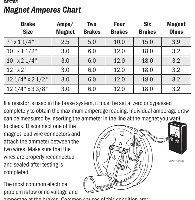
Diagnostic Chart
| Symptom | Check | Spec / Expected | Likely cause & fix |
|---|---|---|---|
| Low or absent brake voltage and current | Start at the controller using its manufacturer's test information, then inspect connections, circuit continuity, wire suitability, broken wires, fuses, and controller or resistor operation. | Use the manufacturer's test information; the lesson provides no numeric output or wire-size limits. | Poor connections, open circuits, insufficient wire size, broken wires, blown fuses, or malfunctioning controllers or resistors. Basis: LDServiceOnline |
| Abnormally high system amperage | Unplug the trailer and observe the current reading to determine whether the fault follows the trailer circuit. | If the high current reading falls to zero after unplugging the trailer, the short is in the trailer. | Shorted or partially shorted circuitry; listed possibilities include shorted magnet coils, defective controllers, and bare wires touching grounded objects. Basis: LDServiceOnline |
| Excessive current traced to the trailer | Disconnect every brake magnet and determine whether excessive current remains in the trailer circuit. | High current remaining with every brake magnet disconnected indicates a trailer-wiring short. | An unintended wiring path to ground, such as bare wire contacting a grounded object. Basis: LDServiceOnline |
| Intermittent braking or brakes that drag | For intermittent braking, inspect broken wires, loose connections, faulty grounds, and controller operation. For dragging brakes, include the breakaway switch in the investigation. | The lesson identifies inspection targets but provides no numeric limits for these symptoms. | Interrupted wiring or ground paths, loose connections, controller faults, or a faulty breakaway switch. Basis: LDServiceOnline |
At the Bay: Diagnose the Case
CASE 1 / 4
Low or absent brake voltage and current
- Test
- Compare
- Correct
Select the next check
Basis: LDServiceOnline. A likely cause is a hypothesis; confirm it with the applicable service procedure before repair.
Common Bay Mistakes
- ✕ Replacing magnets before testing from the controller.
- ✕ Treating a stationary reading as proof that an intermittent fault is gone.
- ✕ Leaving a suspected short energized or bypassing circuit protection during isolation.
- ✕ Returning the trailer to service without verifying the repair; seek professional assistance if the fault cannot be safely identified or corrected.
Quick Check
Practice only — not scored.
Plan the Service Sequence
Planning practice only. Follow the applicable manufacturer's instructions, employer safety program and qualified supervision on real equipment.
Plan the first action. Compare the service steps with the bay mistakes.
Hands-on: Test Bench Practice
Symptom: Healthy trailer. Learn what good readings look like.
Tap a point to place the red probe.
Good system: ~12.6 V at pins, 3.2 Ω across a 12×2-inch magnet (unplugged), 3.0 A per magnet at 12 V full gain, and at least 10.5 V at the magnet — the chart values from the axle manuals.
Hands-on: Shop Test Equipment
IPA #9107B Electric Brake Force Meter
Plugs into the truck's 7-way socket on a 25 ft cable; simulates a trailer load and shows controller output on 10 blue LEDs
🛠 Equip your bay for this test →Symptom: Customer wants the truck checked before buying a trailer.
Spec limits used
- 1–10, each 1.0–1.5 V — Gain LEDs (IPA #9107B manual, p.5)
- 15 s — Max time holding brake pedal (IPA #9107B manual, p.4)
- set-up step 5 — Connect the 9-pin only after the engine is running (IPA #9107B manual, p.3)
- hold brake pedal during ECU detection — 2016–2017 'Trailer Connected' not shown (IPA #9107B manual, p.3)
- faulty brake control module or relay — ECU light never lights on a vehicle with a controller (IPA #9107B manual, p.5)
Simulated readings for practice. Always follow the manufacturer's procedure and values on a real trailer.
Hands-on: Wire-Trace Overlay
Pin 2 · Blue
Electric brakes
- Left and right brake magnets
- Breakaway switch output
Check points
- Two brakes draw about 6.0 A (3.0 A per magnet) at 12 V full gain.
- Unplugged: 3.2 Ω per magnet; at least 10.5 V at each magnet under load.
Common failures
- Open magnet: about half the expected current and a pull to one side.
- Shorted magnet: very low resistance and controller overload.
- Wire chafed where it drops to the axle.
Colors shown are the most common RV harness colors; makers vary — always verify against the trailer's wiring diagram.
Source: LDServiceOnline — 18-23