Correlating Electrical Tests with Brake Condition
- Trace brake application from energized magnet to shoe contact.
- Correlate electrical results with magnet, lining, and linkage condition.
- Apply documented replacement grouping and safe service practices.
- Jack and adequate jack stands — Lift and support the trailer according to the trailer manufacturer's instructions before wheel-end service.
- Straightedge — Check the magnet face for uneven wear and pronounced gaps.
- Inspection light — Examine the magnet for exposed coil material and inspect linings and actuation components.
- Lining thickness gauge — Measure remaining lining thickness and compare it with the applicable manufacturer's replacement limit.
- Digital multimeter — Perform electrical checks using the applicable service procedure; correlate results with physical brake condition rather than treating electrical readings as proof of braking performance.
- Basic hand tools — Access brake components and service hardware according to the applicable manufacturer's instructions.
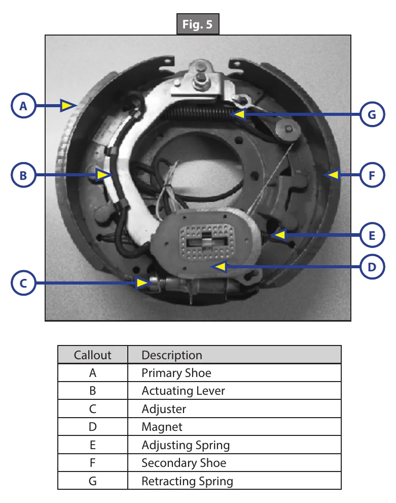
Electrical actuation is only the beginning of brake operation. An energized magnet engages the rotating drum surface and moves the actuating lever. The cam applies the primary shoe, whose force brings the secondary shoe into contact with the drum.
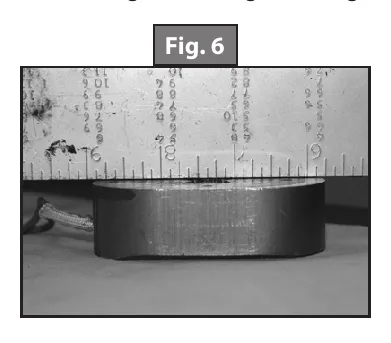
Inspect the magnet face for abnormal or uneven wear using a straightedge. The face should be flat, and pronounced gaps indicate replacement is needed. An exposed coil also requires replacement even when the remaining face appears to have normal wear.
When replacing a magnet, reface the drum armature surface and replace the opposite brake's magnet on the same axle to maintain even braking capacity. Inspect the linings for grease or oil contamination, scoring, pitting, and gouging. Lippert specifies lining replacement at 1/16 inch or less; values vary by maker.
Replace both shoes on a brake and the corresponding shoes on the same axle when replacement is required. Return cleaned parts to their original brake assembly and inspect for loose or worn components. Re-burnish replacement shoes and linings using the applicable instructions, allowing cooling between applications.
How It Works
Electrical operation is not proof of braking
An energized magnet engages the rotating drum surface and moves the actuating lever; the cam applies the primary shoe, whose force brings the secondary shoe into contact with the drum. Electrical testing evaluates the actuation supply and circuit, but useful braking also requires friction contact and a sound mechanical force path. A satisfactory electrical result therefore does not rule out worn friction surfaces or loose or worn actuation components.
Magnet contact and balanced replacement
The magnet face should be flat when checked with a straightedge; pronounced gaps or an exposed coil require replacement. Uneven contact can impair consistent frictional engagement even when the magnet energizes. When replacing a magnet, reface the drum armature surface and replace the opposite brake's magnet on the same axle to maintain even braking capacity.
Lining condition and return to service
Inspect linings for grease or oil contamination, scoring, pitting, and gouging; Lippert specifies replacement at 1/16 inch or less, but limits vary by maker. When shoe replacement is required, replace both shoes on the brake and the corresponding shoes on the same axle, return cleaned parts to their original brake assembly, and inspect for loose or worn components. Re-burnish replacement shoes and linings according to the applicable instructions, allowing cooling between applications so frictional heat can dissipate.
Step-by-Step Procedure
0/7 doneLippert lining limit; values vary by maker
| Lining replacement threshold | 1/16 inch or less |
Figures
Diagnostic Chart
| Symptom | Check | Spec / Expected | Likely cause & fix |
|---|---|---|---|
| Brake remains weak despite an apparently satisfactory electrical test. | Inspect magnet-to-drum contact, lining condition, and the actuating lever and cam path rather than stopping at the electrical result. | Use the applicable service procedure for electrical acceptance criteria; an electrical result alone does not establish mechanical braking performance. | Poor friction contact or lost mechanical motion can prevent electrical actuation from producing effective shoe application. Basis: General shop practice |
| Magnet face shows uneven wear or exposed coil material. | Place a straightedge across the face and look for pronounced gaps; visually inspect for any exposed coil. | The face should be flat. Pronounced gaps or an exposed coil require replacement; reface the drum armature surface and replace the opposite brake's magnet on the same axle. | The magnet has reached a documented replacement condition even if it still energizes. Basis: Lippert-Axle-8K-16K-Manual |
| Linings appear thin, contaminated, or physically damaged. | Measure lining thickness and inspect for grease or oil, scoring, pitting, and gouging. | Lippert lining replacement threshold: 1/16 inch or less; values vary by maker. When replacement is required, replace both shoes on the brake and the corresponding shoes on the same axle. | Lining wear, contamination, or surface damage may account for poor braking despite electrical actuation. Basis: Lippert-Axle-8K-16K-Manual |
| Loose or worn components are found during brake inspection. | Inspect the mechanical actuation path and confirm cleaned parts remain with their original brake assembly. | Inspect for loose or worn components and return cleaned parts to their original brake assembly. Burnish replacement shoes and linings using the applicable instructions, allowing cooling between applications. | Mechanical component condition must be addressed alongside magnet and lining condition. Basis: Lippert-Axle-8K-16K-Manual |
At the Bay: Diagnose the Case
CASE 1 / 4
Brake remains weak despite an apparently satisfactory electrical test.
- Test
- Compare
- Correct
Select the next check
Basis: General shop practice. A likely cause is a hypothesis; confirm it with the applicable service procedure before repair.
Common Bay Mistakes
- ✕ Do not equate an energized magnet with a mechanically healthy brake.
- ✕ Do not retain an exposed-coil magnet because the remaining face looks normally worn.
- ✕ Do not replace only the visibly affected friction component while ignoring the documented axle-wide replacement grouping.
- ✕ Older linings may contain asbestos: avoid creating or breathing dust, never machine linings, and never clean with compressed air or dry brushing.
Quick Check
Practice only — not scored.
Plan the Service Sequence
Planning practice only. Follow the applicable manufacturer's instructions, employer safety program and qualified supervision on real equipment.
Plan the first action. Compare the service steps with the bay mistakes.
Hands-on: Test Bench Practice
Symptom: Healthy trailer. Learn what good readings look like.
Tap a point to place the red probe.
Good system: ~12.6 V at pins, 3.2 Ω across a 12×2-inch magnet (unplugged), 3.0 A per magnet at 12 V full gain, and at least 10.5 V at the magnet — the chart values from the axle manuals.
Hands-on: Shop Test Equipment
IPA #9107B Electric Brake Force Meter
Plugs into the truck's 7-way socket on a 25 ft cable; simulates a trailer load and shows controller output on 10 blue LEDs
🛠 Equip your bay for this test →Symptom: Customer wants the truck checked before buying a trailer.
Spec limits used
- 1–10, each 1.0–1.5 V — Gain LEDs (IPA #9107B manual, p.5)
- 15 s — Max time holding brake pedal (IPA #9107B manual, p.4)
- set-up step 5 — Connect the 9-pin only after the engine is running (IPA #9107B manual, p.3)
- hold brake pedal during ECU detection — 2016–2017 'Trailer Connected' not shown (IPA #9107B manual, p.3)
- faulty brake control module or relay — ECU light never lights on a vehicle with a controller (IPA #9107B manual, p.5)
Simulated readings for practice. Always follow the manufacturer's procedure and values on a real trailer.
Hands-on: Wire-Trace Overlay
Pin 2 · Blue
Electric brakes
- Left and right brake magnets
- Breakaway switch output
Check points
- Two brakes draw about 6.0 A (3.0 A per magnet) at 12 V full gain.
- Unplugged: 3.2 Ω per magnet; at least 10.5 V at each magnet under load.
Common failures
- Open magnet: about half the expected current and a pull to one side.
- Shorted magnet: very low resistance and controller overload.
- Wire chafed where it drops to the axle.
Colors shown are the most common RV harness colors; makers vary — always verify against the trailer's wiring diagram.
Source: Lippert-Axle-8K-16K-Manual — 10-13