Shoe Replacement and Assembly Verification
- Identify shoe orientation and the correct adjuster assembly.
- Replace shoes across the axle while preserving an assembly reference.
- Verify hardware seating, pivot movement, wiring protection, and adjuster operation.
- Floor jack, jack stands, and wheel chocks — Lift and support the trailer securely and prevent movement before exposing the brakes.
- Brake spring pliers — Remove and install brake springs with controlled tension.
- Socket and wrench set — Remove and install brake hardware using the applicable assembly instructions.
- Inch-pound torque wrench — Tighten the covered Dexter anchor-post locknut to 200 in.-lbs.; confirm applicability before using this value.
- Brake adjusting spoon — Retract and position the adjustment screw without overextending the shoes.
- Inspection light and mirror — Inspect shoe-tab seating, spring engagement, cable routing, and hidden wire pinch points.
Replace the shoe and lining set across the axle, but complete one brake at a time so the opposite assembly remains available as a reference. Before reassembly, inspect the magnet, drum, seal, bearings, and spindle. The supplied shoe instruction sheet distinguishes manual-adjust and cable-operated self-adjusting procedures; do not interchange their spring and adjuster details.
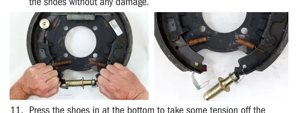
In the covered assembly, the shorter lining identifies the front-facing primary shoe, while the longer lining identifies the rear-facing secondary shoe. Before installing the shoes, clean the loose parts and adjuster threads. Lubricate the adjuster threads and specified contact points, and retract the screw assembly to its shortest length. Keep lubricant away from lining material.
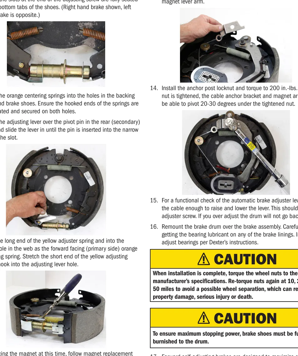
For the cable-operated self-adjusting assembly, verify that the adjuster ends seat fully on the shoe tabs, centering springs are engaged, and the adjusting lever is correctly retained on its pivot. Route the cable around the rear-shoe pulley and connect it to the lever and anchor bracket as directed. Dexter specifies an anchor-post locknut torque of 200 in.-lbs. and requires the bracket and magnet arm to retain 20–30 degrees of pivot movement afterward; these values vary by maker and assembly.
Protect the magnet wiring throughout the job. Restore its clips, anti-chafing sleeve, spring routing, and strain relief rather than allowing the wire to rub or become trapped. Tugging the self-adjuster cable should raise and lower the lever and move the adjustment screw. Avoid overadjusting before drum installation. After assembly, the shoes require burnishing, and forward self-adjustment depends on normal brake applications followed by full release—not deliberate dragging.
How It Works
Balanced replacement and component identity
Replace the shoe and lining set across the axle, completing one brake at a time so the opposite assembly remains available as a reference. In the covered assembly, the shorter lining identifies the front-facing primary shoe and the longer lining identifies the rear-facing secondary shoe; correct placement supports the intended braking action. Identify manual-adjust versus cable-operated self-adjusting construction before selecting spring and adjuster details, because their operating arrangements are not interchangeable.
Clean contact surfaces and free adjustment
Before reassembly, inspect the magnet, drum, seal, bearings, and spindle, then clean reusable loose parts and adjuster threads. Lubricate the adjuster threads and specified contact points while keeping lubricant off the linings, because contamination changes friction and can produce uneven braking. Retract the screw assembly to its shortest length before shoe installation, and verify seated adjuster ends, engaged centering springs, and a correctly retained lever so motion reaches the adjustment screw rather than being lost through misplaced parts.
Retention without binding
For the covered Dexter assembly, tighten the anchor-post locknut to 200 in.-lbs. and verify that the cable anchor bracket and magnet arm retain 20–30 degrees of pivot movement; these requirements vary by maker and assembly. Restore magnet-wire clips, anti-chafing protection, spring routing, and strain relief because rubbing or trapped wiring can interrupt magnet operation and cause loss of braking. Arrange burnishing after assembly, and teach that forward self-adjustment requires normal brake applications followed by full release rather than deliberate dragging, which creates sustained frictional heat.
Step-by-Step Procedure
0/8 doneDexter Covered Shoe-Kit References — Values Vary by Maker and Assembly
| Anchor-post locknut | 200 in.-lbs. |
| Movement after tightening | Cable anchor bracket and magnet arm must pivot 20–30 degrees. |
Figures
Diagnostic Chart
| Symptom | Check | Spec / Expected | Likely cause & fix |
|---|---|---|---|
| Shoe identity or replacement balance is uncertain. | Compare lining lengths and installed orientation with the covered instructions; confirm that replacement is planned across the axle while preserving the opposite assembly as a reference. | Covered assembly: shorter lining faces front as the primary shoe; longer lining faces rear as the secondary shoe. | Primary and secondary shoes may be reversed, or replacement may have been limited to an individual brake. Basis: 05965300BrakeShoeInstructionSheet |
| Tugging the self-adjuster cable does not move the adjustment screw. | Check cable routing around the rear-shoe pulley, connections at the lever and anchor bracket, lever pivot retention, centering springs, and adjuster seating on the shoe tabs. | Tugging the cable should raise and lower the lever and move the adjustment screw; use the cable-operated self-adjusting assembly details. | Misrouted cable, an incorrectly retained lever, unseated adjuster ends, or substituted manual-adjust components may prevent motion transfer. Basis: 05965300BrakeShoeInstructionSheet |
| The cable anchor bracket or magnet arm binds after anchor hardware is secured. | Confirm the assembly identity, applicable torque, hardware arrangement, and retained pivot movement. | Covered Dexter anchor-post locknut: 200 in.-lbs. Cable anchor bracket and magnet arm must pivot 20–30 degrees. | Incorrect hardware assembly or tightening may clamp parts that must remain free to pivot. Basis: 05965300BrakeShoeInstructionSheet |
| Magnet wiring rubs, becomes trapped, or lacks support after shoe installation. | Inspect the wire path and restore clips, anti-chafing sleeve, spring routing, and strain relief before closing the assembly. | Protect the magnet wiring from rubbing and trapping; restore its specified routing and protective components. | Omitted protection or incorrect routing can damage the wiring and cause loss of braking. Basis: 05965300BrakeShoeInstructionSheet |
At the Bay: Diagnose the Case
CASE 1 / 4
Shoe identity or replacement balance is uncertain.
- Test
- Compare
- Correct
Select the next check
Basis: 05965300BrakeShoeInstructionSheet. A likely cause is a hypothesis; confirm it with the applicable service procedure before repair.
Common Bay Mistakes
- ✕ Treating the opposite brake as a substitute for the correct assembly instructions.
- ✕ Mixing manual-adjust and self-adjusting spring or adjuster details.
- ✕ Contaminating linings with lubricant or overadjusting before drum installation.
- ✕ Assuming correct locknut torque guarantees free pivot movement.
Quick Check
Practice only — not scored.
Plan the Service Sequence
Planning practice only. Follow the applicable manufacturer's instructions, employer safety program and qualified supervision on real equipment.
Plan the first action. Compare the service steps with the bay mistakes.
Hands-on: Test Bench Practice
Symptom: Healthy trailer. Learn what good readings look like.
Tap a point to place the red probe.
Good system: ~12.6 V at pins, 3.2 Ω across a 12×2-inch magnet (unplugged), 3.0 A per magnet at 12 V full gain, and at least 10.5 V at the magnet — the chart values from the axle manuals.
Hands-on: Shop Test Equipment
IPA #9107B Electric Brake Force Meter
Plugs into the truck's 7-way socket on a 25 ft cable; simulates a trailer load and shows controller output on 10 blue LEDs
🛠 Equip your bay for this test →Symptom: Customer wants the truck checked before buying a trailer.
Spec limits used
- 1–10, each 1.0–1.5 V — Gain LEDs (IPA #9107B manual, p.5)
- 15 s — Max time holding brake pedal (IPA #9107B manual, p.4)
- set-up step 5 — Connect the 9-pin only after the engine is running (IPA #9107B manual, p.3)
- hold brake pedal during ECU detection — 2016–2017 'Trailer Connected' not shown (IPA #9107B manual, p.3)
- faulty brake control module or relay — ECU light never lights on a vehicle with a controller (IPA #9107B manual, p.5)
Simulated readings for practice. Always follow the manufacturer's procedure and values on a real trailer.
Source: 05965300BrakeShoeInstructionSheet — 1-4