Clearance Adjustment and Controller Synchronization
- Establish uniform shoe-to-drum clearance.
- Distinguish mechanical adjustment from controller gain and timing.
- Verify coordinated braking without sustained skid, jerking, or pushing.
- Floor jack — Lift the trailer at an approved lifting point before placing supports.
- Jack stands — Support the trailer securely while leaving the wheel free to rotate.
- Wheel chocks — Prevent unintended movement during lifting and adjustment.
- Brake adjusting spoon — Turn the starwheel through the backing-plate access opening.
- Flat-blade screwdriver — Remove the access cover and hold the self-adjuster lever away from the starwheel when reverse adjustment requires it.
Mechanical adjustment establishes shoe-to-drum clearance; controller adjustment governs electrical output and braking response. Neither replaces the other. Bostail directs brake adjustment after the first 200 miles and at 3,000-mile intervals afterward, or as use and performance require. These intervals vary by maker. Proper burnishing must precede synchronization testing.
With the trailer safely supported and the wheel free to rotate, remove the backing-plate access cover and expand the shoes with the starwheel until the wheel becomes difficult to turn. Reverse the adjustment until the wheel turns freely with slight lining drag. A self-adjusting brake may require another screwdriver to hold the adjusting lever away from the starwheel during reverse rotation. Restore the cover and obtain uniform clearance across the brakes.
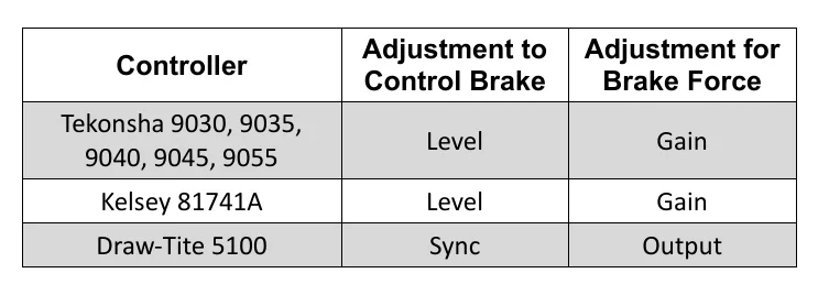
Gain or output generally controls maximum current, while level or synchronization adjustment affects when braking is felt. Remain within the controller manufacturer's instructions. Progressive modulation is important: an immediate jump to high electrical output can cause harsh braking or lockup. Load, road conditions, and electrical supply changes can affect braking response.
Verify synchronization through road testing in an area clear of vehicles and pedestrians. After burnishing, the source describes approaching lockup without deliberately maintaining a skid: reduce gain if the wheels lock and slide, and increase it cautiously if additional output is needed. Not every trailer can lock its wheels. Correct coordination allows trailer braking slightly ahead of the tow vehicle without a sensation of the trailer jerking or pushing.
How It Works
Mechanical clearance establishes the foundation
Expand the shoes until the wheel becomes difficult to turn, then reverse the starwheel until it turns freely with slight lining drag; restore the cover and establish uniform clearance across the brakes. Excessive clearance delays shoe contact, while insufficient clearance creates frictional heat and accelerates wear. Bostail directs adjustment after the first 200 miles and at 3,000-mile intervals afterward, or as use and performance require; verify the applicable maker's schedule rather than treating these intervals as universal.
Gain and timing have different jobs
Gain or output generally controls maximum current, while level or synchronization affects when braking is felt; neither corrects improper mechanical clearance. Progressive electrical output lets braking build smoothly, whereas an immediate jump to high output can cause harsh engagement or lockup. Stay within the controller manufacturer's instructions and account for changes in load, road conditions, and electrical supply.
Burnishing precedes synchronization
Burnishing helps establish effective lining contact with the drum and must precede synchronization testing. The source describes several hard stops from 20 mph on dry pavement free of sand and gravel in an area clear of vehicles and pedestrians, approaching lockup without deliberately maintaining a skid. Reduce gain if wheels lock and slide, increase it cautiously if more output is needed, and seek trailer braking slightly ahead of the tow vehicle without jerking or pushing; not every trailer can lock its wheels.
Step-by-Step Procedure
0/6 doneBostail Adjustment and Test References — Values Vary by Maker
| Initial clearance adjustment | After the first 200 miles. |
| Subsequent clearance adjustment | Every 3,000 miles, or as use and performance require. |
| Post-burnishing gain-setting test | Several hard stops from 20 mph on dry pavement free of sand and gravel, with the test area clear. |
Figures
Diagnostic Chart
| Symptom | Check | Spec / Expected | Likely cause & fix |
|---|---|---|---|
| Wheel remains difficult to turn after clearance adjustment. | With the trailer safely supported, reverse the starwheel and release the self-adjuster lever if it prevents reverse rotation. | The wheel turns freely with slight lining drag; restore the access cover. | Shoes may remain overexpanded, or the self-adjuster lever may prevent backing off the adjustment. Basis: Bostail 8K Axle Manual |
| Trailer pushes the tow vehicle during braking. | Verify uniform mechanical clearance and completed burnishing before evaluating gain and synchronization according to the controller instructions. | Trailer braking slightly ahead of the tow vehicle without jerking or pushing. | Excessive clearance can delay contact; insufficient output or late controller response can also delay effective trailer braking. Basis: Bostail 8K Axle Manual |
| Trailer brakes engage harshly or wheels lock and slide. | Evaluate progressive modulation and controller settings during a road test in a clear area; reduce gain if wheels lock and slide. | Remain within controller adjustment limits and do not deliberately maintain a skid. | Excessive gain or an immediate jump to high electrical output can produce harsh braking or lockup. Basis: Bostail 8K Axle Manual |
| A wheel binds even after the shoes are backed off. | Stop controller tuning and inspect for seized shoe hardware, damaged friction components, or a binding hub bearing before road testing. | No numerical acceptance limit is supplied for these faults; consult the applicable component service instructions. | Mechanical binding outside the normal clearance adjustment can keep the wheel from rotating freely. Basis: General shop practice |
At the Bay: Diagnose the Case
CASE 1 / 4
Wheel remains difficult to turn after clearance adjustment.
- Test
- Compare
- Correct
Select the next check
Basis: Bostail 8K Axle Manual. A likely cause is a hypothesis; confirm it with the applicable service procedure before repair.
Common Bay Mistakes
- ✕ Increasing gain to hide excessive shoe clearance.
- ✕ Leaving the shoes tight instead of backing off to slight lining drag.
- ✕ Synchronizing before burnishing is complete.
- ✕ Treating wheel lockup as a universal requirement or maintaining a skid.
Quick Check
Practice only — not scored.
Plan the Service Sequence
Planning practice only. Follow the applicable manufacturer's instructions, employer safety program and qualified supervision on real equipment.
Plan the first action. Compare the service steps with the bay mistakes.
Hands-on: Test Bench Practice
Symptom: Healthy trailer. Learn what good readings look like.
Tap a point to place the red probe.
Good system: ~12.6 V at pins, 3.2 Ω across a 12×2-inch magnet (unplugged), 3.0 A per magnet at 12 V full gain, and at least 10.5 V at the magnet — the chart values from the axle manuals.
Hands-on: Shop Test Equipment
IPA #9107B Electric Brake Force Meter
Plugs into the truck's 7-way socket on a 25 ft cable; simulates a trailer load and shows controller output on 10 blue LEDs
🛠 Equip your bay for this test →Symptom: Customer wants the truck checked before buying a trailer.
Spec limits used
- 1–10, each 1.0–1.5 V — Gain LEDs (IPA #9107B manual, p.5)
- 15 s — Max time holding brake pedal (IPA #9107B manual, p.4)
- set-up step 5 — Connect the 9-pin only after the engine is running (IPA #9107B manual, p.3)
- hold brake pedal during ECU detection — 2016–2017 'Trailer Connected' not shown (IPA #9107B manual, p.3)
- faulty brake control module or relay — ECU light never lights on a vehicle with a controller (IPA #9107B manual, p.5)
Simulated readings for practice. Always follow the manufacturer's procedure and values on a real trailer.
Source: Bostail 8K Axle Manual — 19-43