Reverse Solenoid Wiring and Profile-Specific Bleeding
- Verify and connect the documented reverse-solenoid circuit.
- Prepare the hydraulic system to release trapped air.
- Bleed and verify operation using the correct actuator-profile procedure.
- Digital multimeter — Identify the reverse-lamp circuit at the connector and check the solenoid ground path rather than trusting wire color.
- Brake-line wrench — Connect the brake line at the solenoid without thread sealant while protecting the fitting flats.
- Bleeder wrench — Control the bleed screw and close it before releasing the pushrod during low-profile bleeding.
- Clear discharge hose and clear receiving container — Observe discharged air and keep the hose end submerged in clean fluid; never return discharged fluid to the reservoir.
- Screwdriver — Operate the standard-profile actuator only after confirming the access-port view and the documented pumping position.
- Pressure bleeder with gauge — Support pressure bleeding when appropriate to the actuator instructions; observe the applicable maker's pressure limit.
The reverse solenoid uses the tow vehicle's reverse-light circuit to assist backing. In the documented arrangement, one solenoid lead connects through the trailer connector to that circuit and the other grounds to the trailer frame; verify the circuit rather than relying only on a usual wire color. Do not apply thread sealant to the brake-line connection at the solenoid.
Prepare the hydraulic system so air can escape. Keep the actuator below the disc calipers when possible, avoid line routing that rises and then falls into an air trap, and place caliper bleeders at the top. Begin at the brake farthest away along the actual brake-line route.
Use fresh fluid and keep the discharge-hose end submerged in clean fluid in a clear container without reusing the discharged fluid. Dexter specifies fresh DOT 3 fluid, a pressure-bleeder maximum of 18 psi, and at least a half-full reservoir during manual bleeding; values and fluid requirements vary by maker.
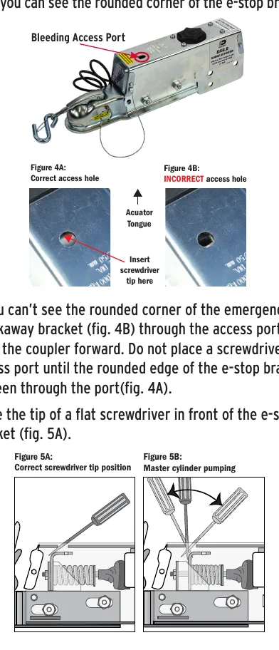
Standard-profile bleeding requires the correct access-port view and screwdriver position ahead of the emergency-stop bracket. Low-profile bleeding uses coordinated pushrod operation and bleed-screw control: close the screw before slowly releasing the pushrod. Continue until air is removed, maintain reservoir level, and complete the profile-specific pressure and release checks.
How It Works
Reverse assistance depends on a verified circuit
The reverse solenoid uses the tow vehicle's reverse-light circuit to assist backing; the documented connection is the center pin of the 7-way connector, verified as the reverse-lamp circuit, with the other lead grounded to the trailer frame. A wire color or connector position alone does not prove circuit function, and resistance at the frame ground can prevent dependable solenoid operation. Connect the brake line at the solenoid without thread sealant.
Air removal requires both routing and fluid control
Air compresses under hydraulic pressure, absorbing actuator movement that should apply the brakes; keep the actuator below the disc calipers when possible, avoid rise-and-fall air traps, and position caliper bleeders at the top. Begin at the brake farthest along the actual brake-line route, keep the discharge-hose end submerged in clean fluid, and discard discharged fluid. Dexter specifies fresh DOT 3 from a fresh container, a pressure-bleeder limit of 18 psi maximum, and a reservoir at least half full during manual bleeding; requirements vary by maker.
Actuator profile determines the bleeding method
For standard-profile bleeding, confirm that the rounded emergency-stop bracket edge is visible before inserting the screwdriver, then use the documented illustrated position ahead of the bracket. For low-profile bleeding, fill the reservoir, clear master-cylinder bubbles with short pushrod strokes while holding the release bracket, and coordinate pushrod movement with bleed-screw control so the screw closes before the pushrod is slowly released. Continue until air is removed, maintain reservoir level, complete the applicable profile-specific pressure and release checks, and restore the final fluid level without overfilling.
Step-by-Step Procedure
0/8 doneDexter surge bleeding references; values vary by maker
| Fluid | Fresh DOT 3 from a fresh container |
| Pressure-bleeder limit | 18 psi maximum |
| Reservoir during manual bleeding | At least half full |
| Documented reverse connection | Center pin of the 7-way connector, verified as the reverse-lamp circuit |
Figures
Diagnostic Chart
| Symptom | Check | Spec / Expected | Likely cause & fix |
|---|---|---|---|
| Reverse assistance does not operate when backing. | Verify reverse-lamp function at the trailer connector, trace the solenoid supply lead, and inspect the other lead's frame-ground connection. | Center pin of the 7-way connector, verified as the reverse-lamp circuit; the other solenoid lead grounds to the trailer frame. | An incorrect connector circuit or ineffective frame ground can prevent the solenoid from operating. Basis: 2024.02LIT75000LightDutyActuatorInstallation |
| Air continues to discharge or brake application remains inconsistent after bleeding. | Inspect bleeder orientation and line routing, confirm the starting brake by actual hydraulic routing, and watch reservoir level throughout bleeding. | Place caliper bleeders at the top; begin at the brake farthest along the brake-line route. Dexter manual-bleeding reservoir requirement: At least half full. | Air may remain trapped at high points or enter the hydraulic system when reservoir level is not maintained. Basis: 2024.02LIT75000LightDutyActuatorInstallation |
| Standard-profile pumping cannot be performed in the documented position. | Stop before inserting or forcing the screwdriver. Confirm that the rounded emergency-stop bracket edge is visible and compare the access-port view with the maker's illustration. | Use the illustrated screwdriver pumping position ahead of the emergency-stop bracket only with the correct access-port view. | Incorrect access-port alignment places the tool outside the intended operating position. Basis: 2024.02LIT75000LightDutyActuatorInstallation |
| Low-profile bleeding repeatedly fails to clear air. | Observe the operator coordination, verify that master-cylinder bubbles were cleared, and confirm bleed-screw closure before slow pushrod release. | Close the bleed screw before slowly releasing the pushrod; maintain reservoir level and continue until air is removed. | Incorrect bleed-screw timing can permit reverse flow during release and undermine air removal. Basis: 2024.02LIT75000LightDutyActuatorInstallation |
At the Bay: Diagnose the Case
CASE 1 / 4
Reverse assistance does not operate when backing.
- Test
- Compare
- Correct
Select the next check
Basis: 2024.02LIT75000LightDutyActuatorInstallation. A likely cause is a hypothesis; confirm it with the applicable service procedure before repair.
Common Bay Mistakes
- ✕ Trusting wire color instead of verifying the reverse-lamp circuit.
- ✕ Applying thread sealant to the solenoid brake-line connection.
- ✕ Reusing discharged fluid or treating Dexter requirements as universal.
- ✕ Mixing actuator-profile methods or skipping pressure and release checks.
Quick Check
Practice only — not scored.
Plan the Service Sequence
Planning practice only. Follow the applicable manufacturer's instructions, employer safety program and qualified supervision on real equipment.
Plan the first action. Compare the service steps with the bay mistakes.
Hands-on: Test Bench Practice
Symptom: Healthy trailer. Learn what good readings look like.
Tap a point to place the red probe.
Good system: ~12.6 V at pins, 3.2 Ω across a 12×2-inch magnet (unplugged), 3.0 A per magnet at 12 V full gain, and at least 10.5 V at the magnet — the chart values from the axle manuals.
Hands-on: Wire-Trace Overlay
Pin 2 · Blue
Electric brakes
- Left and right brake magnets
- Breakaway switch output
Check points
- Two brakes draw about 6.0 A (3.0 A per magnet) at 12 V full gain.
- Unplugged: 3.2 Ω per magnet; at least 10.5 V at each magnet under load.
Common failures
- Open magnet: about half the expected current and a pull to one side.
- Shorted magnet: very low resistance and controller overload.
- Wire chafed where it drops to the axle.
Colors shown are the most common RV harness colors; makers vary — always verify against the trailer's wiring diagram.
Source: 2024.02LIT75000LightDutyActuatorInstallation — 6-7