Hitching and Breakaway Readiness
- Verify ball fit and positive coupler engagement.
- Connect safety restraints and breakaway attachment correctly.
- Distinguish a ready breakaway mechanism from an applied or damaged mechanism.
- Wheel chocks — Secure the trailer against unintended movement during inspection; do not rely on the breakaway mechanism as a parking brake.
- Trailer tongue jack — Control coupler height during seating and lightly lift to check latch engagement.
- Flashlight — Illuminate the inspection opening, latch components, stop button, and underside release tab.
- Inspection mirror — View obscured coupler contact points and the underside release tab without placing fingers in moving parts.
- Shop rag — Remove loose surface dirt that could hide ball damage or prevent a clear visual inspection.
Correct ball fit and positive coupler engagement are essential before towing. The documented self-latching coupler seats over the ball without requiring its handle to be opened first, but its hitch pin must be removed during engagement and fully reinserted after closure.
A manual or lever-lock coupler should close with minimal force. An unseated, oversized, or distorted ball can prevent closure; do not force the handle. Confirm ball seating through the inspection opening and verify contact among the handle, plate, and coupler before checking the latch.
Lightly lift to check that the coupler has latched, then connect safety chains or cables in the documented crossed arrangement or as the trailer manufacturer directs. Attach the actuator breakaway S-hook directly to the tow vehicle, not to the safety chains or cables.
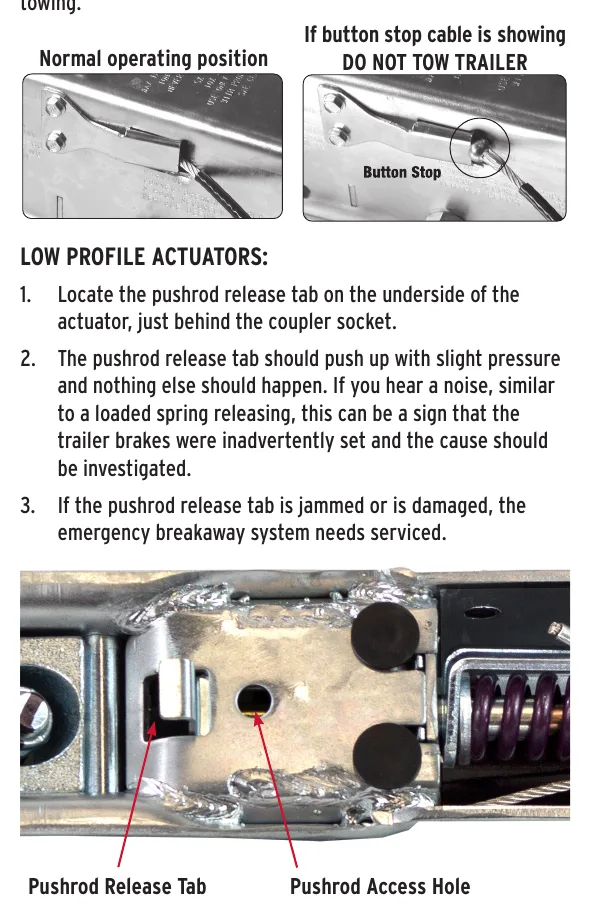
Before towing, verify that the breakaway mechanism is not already engaged. The standard-profile stop button must be in its normal position; on low-profile units, the underside release tab should move with slight pressure without a loaded-spring release sound. Investigate evidence of unintended application and service a jammed or damaged release tab.
How It Works
Ball seating comes before latch verification
Correct ball fit allows the coupler to seat so the latch can retain the ball rather than merely appear closed. The documented self-latching coupler seats without opening its handle first, but its hitch pin must be removed during engagement and fully reinserted after closure. A manual or lever-lock coupler should close with minimal force; resistance calls for investigation, not extra leverage.
Verify engagement through independent observations
Confirm ball seating through the inspection opening and verify contact among the handle, plate, and coupler before checking the latch. Lightly lift to verify retention and securely install the required coupler safety pin before towing. Connect safety chains or cables in the documented crossed arrangement or as the trailer manufacturer directs, and attach the breakaway S-hook directly to the tow vehicle rather than to those restraints.
Ready does not mean already applied
A surge actuator uses relative motion between the trailer and tow vehicle to produce braking, while the breakaway mechanism provides emergency application following separation. Before towing, the standard-profile stop button must be in its normal position, or the low-profile underside release tab must move with slight pressure without a loaded-spring release sound. Evidence of accidental application requires investigation, and a jammed or damaged release tab requires service; the breakaway mechanism is not a parking brake.
Step-by-Step Procedure
0/7 doneFigures
Diagnostic Chart
| Symptom | Check | Spec / Expected | Likely cause & fix |
|---|---|---|---|
| Manual or lever-lock handle resists closure. | Stop applying force. Inspect ball fit and condition, confirm seating through the inspection opening, and check contact among the handle, plate, and coupler. | The coupler should close with minimal force; never force the handle. | An unseated, oversized, or distorted ball can prevent closure. Basis: 2024.02LIT75000LightDutyActuatorInstallation |
| The self-latching coupler hitch pin will not fully reinsert. | Confirm that the pin was removed during engagement and inspect seating, alignment, ball condition, and complete coupler closure before repeating the latch check. | The hitch pin must be removed during engagement and fully reinserted after closure; do not tow without the required safety pin. | Incomplete seating, alignment problems, or ball condition may prevent complete closure and pin installation. Basis: 2024.02LIT75000LightDutyActuatorInstallation |
| Breakaway S-hook is attached to a safety chain or cable. | Trace the breakaway attachment to its actual anchor and inspect the safety-chain or cable arrangement separately. | Attach the actuator breakaway S-hook directly to the tow vehicle, not to the safety chains or cables. Arrange the restraints as documented or as the trailer manufacturer directs. | The breakaway attachment and safety restraints have been incorrectly treated as interchangeable connection points. Basis: 2024.02LIT75000LightDutyActuatorInstallation |
| Stop button is out of its normal position, or the release tab is stiff, damaged, or produces a loaded-spring release sound. | Identify the actuator profile and inspect its corresponding readiness indicator. Investigate unintended application and obtain service for a jammed or damaged mechanism before towing. | The standard-profile stop button must be in its normal position. The low-profile underside release tab should move with slight pressure without a loaded-spring release sound. | The breakaway mechanism may already be applied, or the release tab may be jammed or damaged. Basis: 2024.02LIT75000LightDutyActuatorInstallation |
At the Bay: Diagnose the Case
CASE 1 / 4
Manual or lever-lock handle resists closure.
- Test
- Compare
- Correct
Select the next check
Basis: 2024.02LIT75000LightDutyActuatorInstallation. A likely cause is a hypothesis; confirm it with the applicable service procedure before repair.
Common Bay Mistakes
- ✕ Mistaking a closed-looking handle for verified ball retention.
- ✕ Forcing the handle or hitch pin instead of investigating resistance.
- ✕ Attaching the breakaway S-hook to the safety chains or cables.
- ✕ Using the breakaway mechanism as a parking brake.
Quick Check
Practice only — not scored.
Plan the Service Sequence
Planning practice only. Follow the applicable manufacturer's instructions, employer safety program and qualified supervision on real equipment.
Plan the first action. Compare the service steps with the bay mistakes.
Hands-on: Test Bench Practice
Symptom: Healthy trailer. Learn what good readings look like.
Tap a point to place the red probe.
Good system: ~12.6 V at pins, 3.2 Ω across a 12×2-inch magnet (unplugged), 3.0 A per magnet at 12 V full gain, and at least 10.5 V at the magnet — the chart values from the axle manuals.
Hands-on: Wire-Trace Overlay
Pin 2 · Blue
Electric brakes
- Left and right brake magnets
- Breakaway switch output
Check points
- Two brakes draw about 6.0 A (3.0 A per magnet) at 12 V full gain.
- Unplugged: 3.2 Ω per magnet; at least 10.5 V at each magnet under load.
Common failures
- Open magnet: about half the expected current and a pull to one side.
- Shorted magnet: very low resistance and controller overload.
- Wire chafed where it drops to the axle.
Colors shown are the most common RV harness colors; makers vary — always verify against the trailer's wiring diagram.
Source: 2024.02LIT75000LightDutyActuatorInstallation — 8-9