Surge Actuator Selection and Installation
- Match the actuator to the brakes, coupler, and towing-system ratings.
- Select the correct mounting procedure and preserve telescoping clearance.
- Inspect mounting, hydraulic routing, and reverse-operation provisions.
- Load-rated jack stands — Support the trailer securely before working underneath; do not support it by its axle or suspension.
- Torque wrench and sockets — Tighten applicable bolt-on mounting hardware to the documented requirement.
- Caliper — Measure tongue material thickness to determine whether the documented spacer-tube requirement applies.
- Spirit level — Check trailer attitude on level ground so the tongue is parallel to the ground.
- Flare-nut wrenches — Service brake-line connections while reducing the risk of rounding fitting flats.
A surge actuator responds to the trailer pushing toward the tow vehicle. Its telescoping movement loads the master cylinder, which sends hydraulic pressure to the trailer brakes; equipment that restricts that movement interferes with the actuation method.
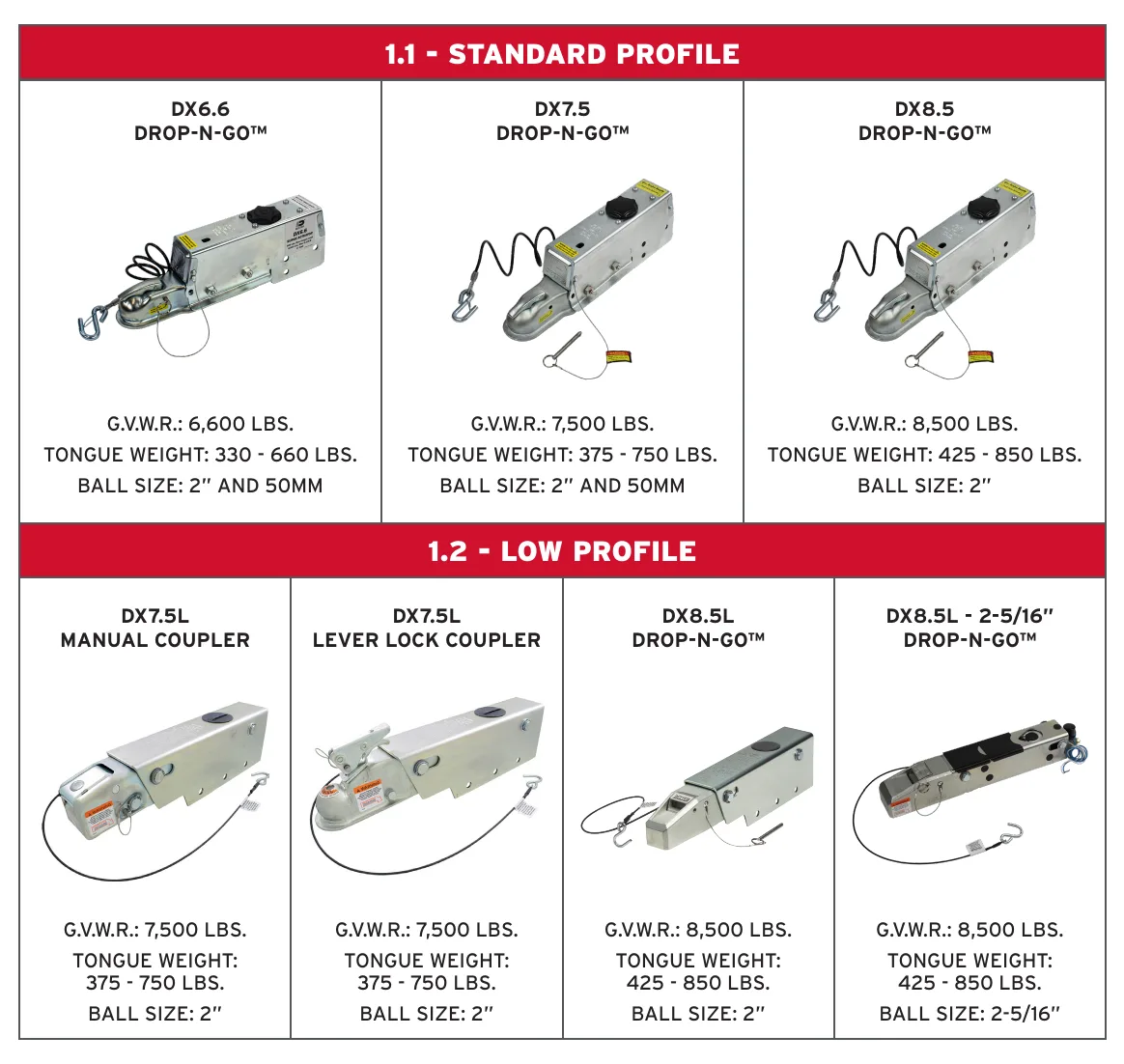
The replacement actuator must match the installed brake system. In the documented installation family, disc and drum actuators are not interchangeable, disc versions require an electric reverse solenoid, and drum versions require free-backing brakes. Identify the actuator profile and coupler before selecting the installation procedure.
Check the actuator rating, ball requirement, trailer rating, and tow-vehicle and hitch limitations together. The tongue should be parallel to the ground for proper actuator operation. Do not compensate for wear or incorrect ball fit by modifying the coupler latch.
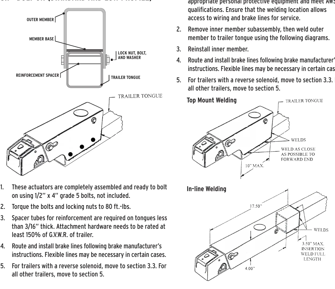
Mounting must preserve structural support and access to brake lines and wiring. The bolt-on method requires the documented hardware and reinforcement, while the low-profile weld-on method requires removal of the inner assembly before welding. In-line welding must leave room for the inner slide, master cylinder, and solenoid to move rearward.
How It Works
Telescoping movement creates brake pressure
When the trailer pushes toward the tow vehicle, the actuator telescopes and loads the master cylinder, producing hydraulic pressure at the brakes. Mounting obstructions, hitch equipment, or poorly routed lines can resist that movement and interfere with brake application or release. Preserve rearward clearance for the inner slide, master cylinder, and solenoid rather than judging clearance only with the actuator extended.
Compatibility includes brakes and the complete hitch system
In the documented installation family, disc and drum actuators are not interchangeable: disc versions require an electric reverse solenoid, while drum versions require free-backing brakes. Identify the actuator profile and coupler, then check the actuator rating, ball requirement, trailer rating, and tow-vehicle and hitch limitations together. Keep the tongue parallel to the ground, and never modify the coupler latch to disguise wear or incorrect ball fit.
Mounting must carry load without binding the actuator
The documented bolt-on method specifies 1/2 × 4 in Grade 5 bolts, bolt and locking-nut torque of 80 ft-lb, and attachment hardware rated at least 150% of trailer GVWR. Spacer tubes are required for tongues less than 3/16 in thick; they support the tongue against crushing under mounting clamp load. For the low-profile weld-on method, remove the inner assembly before welding and use an AWS-qualified welder following the illustrated arrangement, preserving operating clearance and service access before reinstalling the assembly.
Step-by-Step Procedure
0/7 doneDexter actuator installation references; values vary by maker
| Bolt-on hardware | 1/2 × 4 in Grade 5 bolts |
| Bolt and locking-nut torque | 80 ft-lb |
| Reinforcement requirement | Spacer tubes required for tongues less than 3/16 in thick |
| Attachment hardware rating | At least 150% of trailer GVWR |
Figures
Diagnostic Chart
| Symptom | Check | Spec / Expected | Likely cause & fix |
|---|---|---|---|
| Braking is weak or inconsistent after actuator installation. | Inspect for equipment or mounting features that restrict telescoping; check rearward clearance and whether lines or wiring become taut during movement. | Preserve telescoping movement and rearward clearance for the inner slide, master cylinder, and solenoid; route brake lines according to the brake manufacturer's instructions. | Restricted travel can prevent the actuator from loading the master cylinder as intended. Basis: 2024.02LIT75000LightDutyActuatorInstallation |
| Trailer brakes resist backing after actuator replacement. | Identify the installed brake type and actuator version; verify the required reverse provision and applicable solenoid connection procedure. | In the documented installation family, disc versions require an electric reverse solenoid, and drum versions require free-backing brakes. | An incompatible actuator or missing reverse provision can allow backing forces to apply the brakes. Basis: 2024.02LIT75000LightDutyActuatorInstallation |
| Bolt-on mounting is loose or the tongue shows distortion near the bolts. | Verify hardware, locking nuts, tongue thickness, spacer tubes, and tightening against the applicable installation procedure; inspect for damage before further tightening. | 1/2 × 4 in Grade 5 bolts; 80 ft-lb; Spacer tubes required for tongues less than 3/16 in thick; attachment hardware rating: At least 150% of trailer GVWR. | Incorrect hardware, inadequate reinforcement, or improper tightening can compromise mounting support. Basis: 2024.02LIT75000LightDutyActuatorInstallation |
| Coupler fit is questionable or the trailer tongue is not level. | Confirm the specified hitch ball, inspect the coupler for wear or alteration, and review towing-component ratings and trailer attitude. | The tongue should be parallel to the ground; do not modify the coupler latch to compensate for wear or incorrect ball fit. | Incorrect ball fit or coupler wear compromises coupling, while incorrect trailer attitude can interfere with proper actuator operation. Basis: 2024.02LIT75000LightDutyActuatorInstallation |
At the Bay: Diagnose the Case
CASE 1 / 4
Braking is weak or inconsistent after actuator installation.
- Test
- Compare
- Correct
Select the next check
Basis: 2024.02LIT75000LightDutyActuatorInstallation. A likely cause is a hypothesis; confirm it with the applicable service procedure before repair.
Common Bay Mistakes
- ✕ Treating these documented mounting values as universal across actuator manufacturers.
- ✕ Checking clearance only with the actuator extended.
- ✕ Welding the low-profile mount with the inner assembly still installed.
- ✕ Working underneath without load-rated jack stands or supporting the trailer by its axle or suspension.
Quick Check
Practice only — not scored.
Plan the Service Sequence
Planning practice only. Follow the applicable manufacturer's instructions, employer safety program and qualified supervision on real equipment.
Plan the first action. Compare the service steps with the bay mistakes.
Hands-on: Test Bench Practice
Symptom: Healthy trailer. Learn what good readings look like.
Tap a point to place the red probe.
Good system: ~12.6 V at pins, 3.2 Ω across a 12×2-inch magnet (unplugged), 3.0 A per magnet at 12 V full gain, and at least 10.5 V at the magnet — the chart values from the axle manuals.
Hands-on: Wire-Trace Overlay
Pin 2 · Blue
Electric brakes
- Left and right brake magnets
- Breakaway switch output
Check points
- Two brakes draw about 6.0 A (3.0 A per magnet) at 12 V full gain.
- Unplugged: 3.2 Ω per magnet; at least 10.5 V at each magnet under load.
Common failures
- Open magnet: about half the expected current and a pull to one side.
- Shorted magnet: very low resistance and controller overload.
- Wire chafed where it drops to the axle.
Colors shown are the most common RV harness colors; makers vary — always verify against the trailer's wiring diagram.
Source: 2024.02LIT75000LightDutyActuatorInstallation — 3-6