Read the Brake Wiring Information
- Distinguish brake output, battery charge, ground, and breakaway connections.
- Interpret connector terminals using the stated viewing direction.
- Select applicable wire-chart guidance and identify connection faults.
- Digital multimeter — Trace circuit functions and check voltage and voltage drop; isolate power before resistance or continuity testing.
- Tape measure — Measure hitch-to-axle distance for the applicable wire-chart row.
- Inspection light — Inspect terminal markings, conductor condition, corrosion, and damaged seals.
- Wire stripper and terminal crimper — Prepare conductors and secure compatible replacement terminals without damaging wire strands.
- Heat gun — Shrink compatible adhesive-lined tubing when sealing repaired connections.
The typical wiring illustration identifies the electric-brake circuit, battery-charge circuit, common ground, battery, and breakaway switch. Read these as separate circuit functions rather than treating every battery-related wire as a brake-output wire.
Connector illustrations must be read from the stated viewpoint. The supplied wiring page identifies its receptacle views as looking into the tow-vehicle receptacle, which matters when interpreting terminal locations.
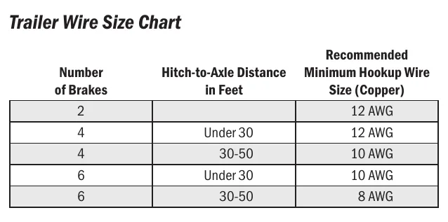
The wire-size chart selects minimum copper hookup wire size using brake count and hitch-to-axle distance. Dexter lists 12 AWG for four brakes under 30 feet and 8 AWG for six brakes at 30–50 feet; values vary by maker and application.
Connection condition affects brake performance. Loose or corroded connectors increase resistance and reduce the voltage available at the brake magnets, so the manual recommends sealing brake-wiring connection points against corrosion.
How It Works
Identify functions before tracing wires
The wiring illustration separates electric-brake output, battery charge, common ground, battery, and breakaway-switch connections. The charge circuit replenishes the battery, while the breakaway circuit allows stored battery energy to operate the brakes when the switch activates. Trace each function using the applicable trailer information rather than treating every battery-related conductor as brake output.
Connector viewpoint controls terminal interpretation
The supplied page shows receptacle views looking into the tow-vehicle receptacle. Viewing a connector from its wiring side changes the apparent terminal arrangement, so matching positions without checking the viewpoint can connect the wrong circuits. A sample illustration is not a universal terminal layout.
Conductor size and connection resistance
Select minimum copper hookup-wire size using both brake count and hitch-to-axle distance: Dexter lists 12 AWG for four brakes under 30 feet and 8 AWG for six brakes at 30–50 feet. Longer conductors and greater brake loads make resistance-related voltage loss more significant, while loose or corroded connections add unwanted resistance. Apply the maker's chart and seal brake-wiring connection points against corrosion.
Step-by-Step Procedure
0/6 doneDexter copper hookup-wire examples; values vary by maker
| Four brakes, hitch-to-axle distance under 30 feet | 12 AWG minimum |
| Six brakes, hitch-to-axle distance 30–50 feet | 8 AWG minimum |
Figures
Diagnostic Chart
| Symptom | Check | Spec / Expected | Likely cause & fix |
|---|---|---|---|
| Circuit behavior does not match the expected connector terminal. | Find the applicable wiring information, confirm the connector-view description, and trace brake output separately from battery charge and breakaway connections. | The supplied receptacle illustrations are looking into the tow-vehicle receptacle; do not treat the sample layout as universal. | The connector was interpreted from the wrong viewpoint or a sample terminal layout was assumed to apply. Basis: LDServiceOnline |
| Low or missing voltage and current at the brakes. | Verify brake count, measure hitch-to-axle distance, and compare the installed copper conductor size with the applicable maker's chart. | Four brakes, hitch-to-axle distance under 30 feet: 12 AWG minimum. Six brakes, hitch-to-axle distance 30–50 feet: 8 AWG minimum. Values vary by maker. | Insufficient wire size contributes to voltage loss in the brake circuit. Basis: LDServiceOnline |
| Weak or intermittent braking with loose or corroded connectors. | Inspect brake-wiring connection points for looseness, corrosion, and failed sealing; repair the connection before sealing it. | Seal brake-wiring connection points against corrosion. | Loose or corroded connections increase resistance and reduce voltage available at the brake magnets. Basis: LDServiceOnline |
| Voltage appears available with the brakes inactive, but braking remains weak when commanded. | With the trailer secured and brakes commanded according to the applicable procedure, check voltage drop across suspect feed and ground connections. | Use the applicable service procedure and acceptance criteria; an unloaded voltage reading alone does not establish connection quality. | A resistive connection may pass enough current for a meter reading but restrict current when the brakes draw power. Basis: General shop practice |
At the Bay: Diagnose the Case
CASE 1 / 4
Circuit behavior does not match the expected connector terminal.
- Test
- Compare
- Correct
Select the next check
Basis: LDServiceOnline. A likely cause is a hypothesis; confirm it with the applicable service procedure before repair.
Common Bay Mistakes
- ✕ Mistaking battery-charge wiring for brake-output wiring.
- ✕ Reading terminal positions without confirming the connector viewpoint.
- ✕ Selecting wire size without checking both brake count and hitch-to-axle distance.
- ✕ Sealing over a loose or corroded connection instead of repairing it.
Quick Check
Practice only — not scored.
Plan the Service Sequence
Planning practice only. Follow the applicable manufacturer's instructions, employer safety program and qualified supervision on real equipment.
Plan the first action. Compare the service steps with the bay mistakes.
Hands-on: Test Bench Practice
Symptom: Healthy trailer. Learn what good readings look like.
Tap a point to place the red probe.
Good system: ~12.6 V at pins, 3.2 Ω across a 12×2-inch magnet (unplugged), 3.0 A per magnet at 12 V full gain, and at least 10.5 V at the magnet — the chart values from the axle manuals.
Hands-on: Shop Test Equipment
IPA #9101 Light Ranger MUTT Trailer Tester
Battery-powered tester with a 7-way flat socket and rotary knob — powers one trailer circuit at a time, up to 10 A
🛠 Equip your bay for this test →Symptom: Pre-delivery inspection on a new utility trailer.
Spec limits used
- 10 A @ 12 V DC — Max output per circuit (IPA #9101/#9102 manual, p.5)
- 30 s — Thermal breaker cooldown (IPA #9101/#9102 manual, p.5)
- 11.5 V tester battery — Never operate below (IPA #9101/#9102 manual, p.6)
- 12.2 V — Verify battery charged to at least (IPA #9101/#9102 manual, p.10)
- battery on the trailer detected — Power LED on with knob OFF (IPA #9101/#9102 manual, p.6)
- 3.0 A each — Brake magnet current (warm) (Dexter magnet data (simulator basis))
Simulated readings for practice. Always follow the manufacturer's procedure and values on a real trailer.
Hands-on: Wire-Trace Overlay
Pin 2 · Blue
Electric brakes
- Left and right brake magnets
- Breakaway switch output
Check points
- Two brakes draw about 6.0 A (3.0 A per magnet) at 12 V full gain.
- Unplugged: 3.2 Ω per magnet; at least 10.5 V at each magnet under load.
Common failures
- Open magnet: about half the expected current and a pull to one side.
- Shorted magnet: very low resistance and controller overload.
- Wire chafed where it drops to the axle.
Colors shown are the most common RV harness colors; makers vary — always verify against the trailer's wiring diagram.
Source: LDServiceOnline — 11-12, 22-23