Measure the Electric-Brake Circuit
- Select the correct chart for the installed brakes.
- Measure brake voltage and current with correct meter connections.
- Interpret circuit readings without claiming battery-capacity results.
- Digital voltmeter — Measure voltage across the magnet lead wires at a brake.
- Series ammeter — Measure circuit or individual magnet current after verifying adequate capacity and correct polarity.
- Insulated hand tools — Open and restore accessible controller-output or magnet-lead connections without damaging terminals.
- Wire stripper and crimping tool — Restore disturbed wiring with suitable sealed connections when repair is needed.
- Wheel chocks — Secure the trailer and tow vehicle against unintended movement during testing.
A voltmeter measures system voltage across the magnet lead wires at a brake. For the controller-operated check described here, the tow-vehicle engine should run so a low tow-vehicle battery does not distort the readings.
An ammeter measures current flowing through the brake circuit. The manual describes disconnecting the controller’s brake-output wire and inserting the meter in series; adequate meter capacity and correct polarity are necessary to avoid meter damage.
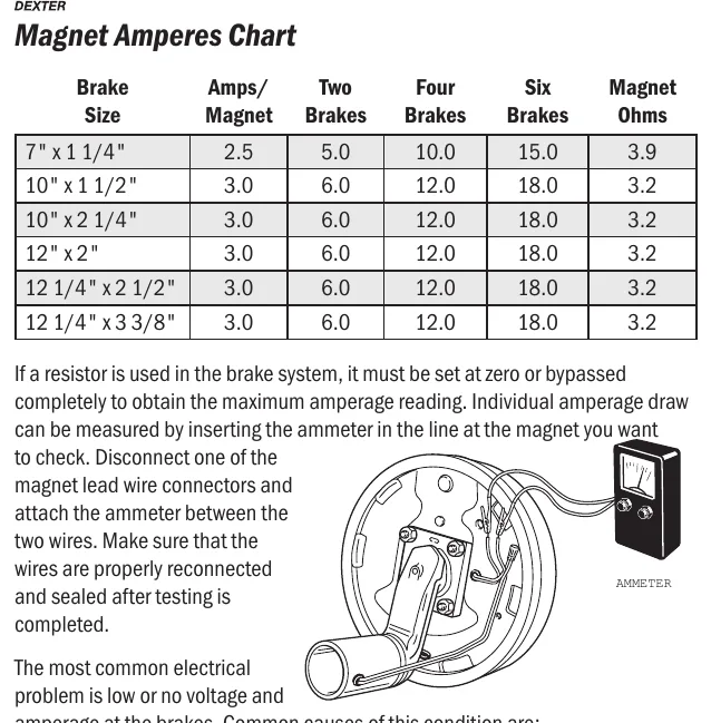
Individual magnet current can be checked by opening a magnet-lead connection and placing the ammeter between the disconnected wires. If a system resistor is present, the manual calls for setting it to zero or bypassing it to obtain the maximum-current reading.
Compare measurements with the chart for the installed brake size and quantity, not with an unrelated brake row. Dexter lists 3.0 amperes per magnet for the 12 by 2 inch brake in this chart; values vary by maker. Reconnect and seal wires after testing.
How It Works
Voltage and current answer different questions
A voltmeter connects across the magnet lead wires to measure the electrical potential available at the brake, while a series ammeter measures current flowing through the circuit. Voltage alone does not establish that the magnet is drawing the expected current; an open circuit can prevent current flow even when voltage is available.
Test conditions determine whether comparison is valid
For the documented controller-operated check, connect the trailer and run the tow-vehicle engine so a low tow-vehicle battery does not distort the readings. For the specified maximum-current reading, set an installed system resistor to zero or bypass it. Compare the result with the chart for the installed brake size and quantity, because magnet design and the number of connected brakes affect current demand.
Protect the meter and preserve the circuit
Verify ammeter capacity and polarity before inserting it in series at the controller brake output or an opened magnet-lead connection. Reconnect and seal disturbed wiring afterward, because loose or moisture-contaminated connections can introduce resistance and corrosion. These controller-operated measurements evaluate the brake circuit; they are not the supplied procedure for testing breakaway-battery capacity.
Step-by-Step Procedure
0/7 doneDexter chart example for 12 by 2 inch electric brakes; values vary by maker
| Current per magnet | 3.0 A |
| Current for four brakes | 12.0 A |
Figures
Diagnostic Chart
| Symptom | Check | Spec / Expected | Likely cause & fix |
|---|---|---|---|
| Controller-operated voltage readings appear unexpectedly low. | Confirm that the trailer is connected, the tow-vehicle engine is running, and the voltmeter is connected across the magnet lead wires. | Use the documented controller-operated test conditions; the lesson supplies no numerical voltage limit. | A low tow-vehicle battery can distort readings when the documented running-engine condition is omitted. Basis: LDServiceOnline |
| An individual magnet draws less current than the applicable chart indicates. | Verify brake identification, insert the ammeter in series at the opened magnet lead, and set an installed system resistor to zero or bypass it for the maximum-current check. | Dexter chart example for a 12 by 2 inch brake: 3.0 A per magnet; values vary by maker. | An unrelated chart entry or a system resistor left in circuit can make the comparison misleading. Basis: LDServiceOnline |
| Total brake current does not match the expected chart entry. | Confirm the installed brake size and quantity, verify meter capacity and polarity, and measure in series at the disconnected controller brake-output wire. | Dexter chart example for four 12 by 2 inch brakes: 12.0 A. | Comparison with the wrong brake quantity or brake-size entry can produce an incorrect diagnosis. Basis: LDServiceOnline |
| Current becomes intermittent after wiring has been disturbed. | With the circuit de-energized, inspect disturbed connections for loose crimps, damaged conductors, corrosion, and incomplete sealing. | Restore secure, sealed connections before returning the circuit to service. | A loose connection can interrupt current; corrosion or damaged strands can increase resistance and reduce current. Basis: General shop practice |
At the Bay: Diagnose the Case
CASE 1 / 4
Controller-operated voltage readings appear unexpectedly low.
- Test
- Compare
- Correct
Select the next check
Basis: LDServiceOnline. A likely cause is a hypothesis; confirm it with the applicable service procedure before repair.
Common Bay Mistakes
- ✕ Connecting an ammeter across magnet leads instead of inserting it in series.
- ✕ Using an undersized ammeter or incorrect polarity.
- ✕ Applying a Dexter example to an unrelated brake size or maker.
- ✕ Treating controller-operated circuit readings as proof of breakaway-battery capacity.
Quick Check
Practice only — not scored.
Plan the Service Sequence
Planning practice only. Follow the applicable manufacturer's instructions, employer safety program and qualified supervision on real equipment.
Plan the first action. Compare the service steps with the bay mistakes.
Hands-on: Test Bench Practice
Symptom: Healthy trailer. Learn what good readings look like.
Tap a point to place the red probe.
Good system: ~12.6 V at pins, 3.2 Ω across a 12×2-inch magnet (unplugged), 3.0 A per magnet at 12 V full gain, and at least 10.5 V at the magnet — the chart values from the axle manuals.
Hands-on: Shop Test Equipment
IPA #9101 Light Ranger MUTT Trailer Tester
Battery-powered tester with a 7-way flat socket and rotary knob — powers one trailer circuit at a time, up to 10 A
🛠 Equip your bay for this test →Symptom: Pre-delivery inspection on a new utility trailer.
Spec limits used
- 10 A @ 12 V DC — Max output per circuit (IPA #9101/#9102 manual, p.5)
- 30 s — Thermal breaker cooldown (IPA #9101/#9102 manual, p.5)
- 11.5 V tester battery — Never operate below (IPA #9101/#9102 manual, p.6)
- 12.2 V — Verify battery charged to at least (IPA #9101/#9102 manual, p.10)
- battery on the trailer detected — Power LED on with knob OFF (IPA #9101/#9102 manual, p.6)
- 3.0 A each — Brake magnet current (warm) (Dexter magnet data (simulator basis))
Simulated readings for practice. Always follow the manufacturer's procedure and values on a real trailer.
Hands-on: Wire-Trace Overlay
Pin 2 · Blue
Electric brakes
- Left and right brake magnets
- Breakaway switch output
Check points
- Two brakes draw about 6.0 A (3.0 A per magnet) at 12 V full gain.
- Unplugged: 3.2 Ω per magnet; at least 10.5 V at each magnet under load.
Common failures
- Open magnet: about half the expected current and a pull to one side.
- Shorted magnet: very low resistance and controller overload.
- Wire chafed where it drops to the axle.
Colors shown are the most common RV harness colors; makers vary — always verify against the trailer's wiring diagram.
Source: LDServiceOnline — 21-23