Service Equalizer and Shackle Connections
- Support the frame and axles to control movement during disassembly.
- Install equalizer and shackle hardware with correct seating and orientation.
- Verify assembly-specific tightening and upright shackle positions.
- Shop jack — Control axle position and assist with even lowering; do not use as the sole support.
- Frame support stands — Support the trailer framework according to the trailer manufacturer's instructions.
- Axle support stands — Support the axles near the U-bolt plates before disconnecting shackles.
- Sockets and ratchet — Remove wheels and loosen or install suspension nuts with correctly fitting sockets.
- Combination wrenches — Hold pressed-in bolts against rotation while removing their nuts.
- Torque wrench — Tighten equalizer and shackle nuts to the applicable assembly specification.
Support the trailer framework according to its manufacturer's instructions, remove the wheels, and support the axles near the U-bolt plates. These additional supports prevent the axles from swinging down when the shackle connections are removed.
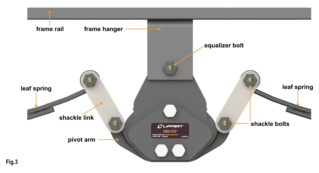
The documented assembly uses bolts pressed into shackle plates and potentially into the frame hanger. Hold these bolts against rotation while removing their nuts. Disconnect the front and rear spring shackles from the equalizer before removing the equalizer cross bolt and equalizer.
For the illustrated replacement design, install the equalizer bolt through the outer hanger plate, upper bronze bushing, and inner hanger plate, then seat its head against the hanger. Install both equalizer and shackle bolts from outside toward the chassis center to keep their threaded ends clear of other assemblies.
Restore the axles to their operating position and fit new shackle links, bolts, and nuts as directed. Lippert specifies 30–50 ft-lb with the nuts bottomed on the bolt shoulders for this assembly; values vary by maker and design. Complete both sides and lower the trailer evenly, checking that the shackle links remain upright in the illustrated positions.
How It Works
Control the load before opening the connection
Frame supports carry the trailer, while separate supports near the U-bolt plates prevent the axles from swinging down when shackles are disconnected. Uncontrolled axle movement can pull brake wiring and damage suspension components. Disconnect the front and rear spring shackles from the equalizer before removing the equalizer cross bolt.
Protect the fit and establish correct seating
The documented bolts are pressed into shackle plates and potentially into the frame hanger; holding them stationary during nut removal helps protect that fit. For the illustrated replacement, pass the equalizer bolt through the outer hanger plate, upper bronze bushing, and inner hanger plate, then seat its head against the hanger. Install equalizer and shackle bolts from outside toward the chassis center to keep threaded ends clear of other assemblies.
Tightening and final geometry are separate checks
For the illustrated Lippert assembly, the equalizer and shackle nuts require 30–50 ft-lb, bottomed against the bolt shoulder; do not transfer this requirement to a different design without confirming its instructions. Restore the axles to operating position and install new shackle links, bolts, and nuts as directed. Complete both sides and lower evenly while checking that the links remain upright, approximately 10 o'clock and 2 o'clock.
Step-by-Step Procedure
0/7 doneLippert illustrated equalizer assembly; values vary by maker and design
| Equalizer and shackle nuts | 30–50 ft-lb, bottomed against the bolt shoulder |
| Shackle positions after lowering | Upright, approximately 10 o'clock and 2 o'clock |
Figures
Diagnostic Chart
| Symptom | Check | Spec / Expected | Likely cause & fix |
|---|---|---|---|
| An axle starts moving downward as a shackle connection is released. | Stop disassembly and verify frame support and separate axle support near the U-bolt plates before continuing. | Support the framework according to its manufacturer's instructions and support the axles near the U-bolt plates. | The axle is not adequately restrained after the shackle load path is opened. Basis: ccd-0011275 |
| A pressed-in bolt turns while its nut is being removed. | Hold the bolt against rotation and inspect the bolt-to-plate or hanger fit for damage before reuse decisions. | Hold pressed-in bolts against rotation while removing their nuts. | The bolt is not being held stationary, or its press fit may have been compromised. Basis: ccd-0011275 |
| Hardware seating or installed clearance is questionable. | Verify the equalizer bolt path through the hanger and upper bronze bushing, head seating, outside-inward orientation, and nut contact with the bolt shoulders. | Illustrated Lippert equalizer and shackle nuts: 30–50 ft-lb, bottomed against the bolt shoulder; values vary by maker and design. | Incorrect bolt orientation, incomplete seating, or use of a tightening procedure for another design. Basis: ccd-0011275 |
| A shackle link folds out of its illustrated upright position during lowering. | Stop lowering, safely support the assembly, and recheck axle position and shackle orientation before resuming even lowering. | Upright, approximately 10 o'clock and 2 o'clock. | Axle position was not restored correctly, or uneven or abrupt lowering allowed the link to change position. Basis: ccd-0011275 |
At the Bay: Diagnose the Case
CASE 1 / 4
An axle starts moving downward as a shackle connection is released.
- Test
- Compare
- Correct
Select the next check
Basis: ccd-0011275. A likely cause is a hypothesis; confirm it with the applicable service procedure before repair.
Common Bay Mistakes
- ✕ Treating frame support as a substitute for separate axle support.
- ✕ Allowing pressed-in bolts to spin during nut removal.
- ✕ Applying the illustrated Lippert torque to every suspension design.
- ✕ Dropping the trailer abruptly instead of watching shackle orientation during even lowering.
Quick Check
Practice only — not scored.
Plan the Service Sequence
Planning practice only. Follow the applicable manufacturer's instructions, employer safety program and qualified supervision on real equipment.
Plan the first action. Compare the service steps with the bay mistakes.
Hands-on: Shop Test Equipment
Dial Indicator — Bearing End Play
Magnetic-base dial indicator (0.001 in) on the hub face, spindle nut adjustment
🛠 Equip your bay for this test →Symptom: Bearing service — set end play after repack.
Spec limits used
- 0.001–0.010 in — Allowable end play, double-nut wheel end (Dexter 9-15K service manual, p.64)
- 0.008 in — Nev-R-Lube 50 mm max axial end play (Dexter 059-831-00)
- illustrative only — Face runout limit (General shop practice)
Simulated readings for practice. Always follow the manufacturer's procedure and values on a real trailer.
Source: ccd-0011275 — 3-4