Inspect a Torsion Suspension System
- Identify the torsion suspension components and trace their load path.
- Inspect mounting hardware, bracket condition, and washer placement.
- Evaluate swing-arm movement and alignment using applicable maker guidance.
- Wheel chocks — Prevent unintended trailer movement during inspection.
- Floor jack and jack stands — Raise and securely support the trailer at maker-approved locations when unloading the suspension is necessary.
- Inspection light and mirror — Examine bracket edges, connections, and concealed surfaces for damage or missing hardware.
- Socket and wrench set — Remove damaged fasteners and install applicable replacement hardware.
- Torque wrench — Tighten mounting fasteners to the applicable torsion-axle specifications.
- Tape measure — Compare axle-position measurements using the maker's alignment procedure and reference points.
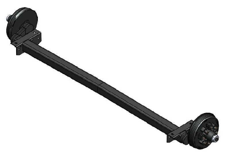
The documented torsion design provides independent wheel-end suspension and uses fewer moving parts than a leaf-spring system. Its suspension mechanism is housed inside the axle tube and attached to the trailer frame through brackets.
A spindle connects to a swing arm linked to a square inner bar. Rubber cords surround the bar inside the axle tube. As road input rotates the swing arm, the cords resist that movement and distribute the resulting loads.
During installation, attach the axle bracket to the frame bracket and tighten fasteners to the applicable torsion-axle specifications. Place washers against slotted holes in the axle bracket; the documented low-profile brackets instead have plain round holes.
Inspection includes wear, deformation, cracks, chafing, missing hardware, and loose connections. Check secure frame mounting, swing-arm movement, and axle alignment. Bostail specifies inspection annually or every 36,000 miles, whichever comes first, for this system; intervals and fastener values vary by maker.
How It Works
How torsion suspension resists road input
The spindle connects to a swing arm linked to a square inner bar, with rubber cords surrounding that bar inside the axle tube. Road input rotates the arm and bar, deforming the rubber cords so they resist movement and distribute the resulting loads. This documented design provides independent wheel-end suspension with fewer moving parts than a leaf-spring system.
Why mounting integrity matters
The axle bracket attaches to the frame bracket, transferring suspension loads into the trailer frame. Loose connections permit relative movement that can wear contact surfaces and increase stress around holes and bracket edges. Place washers against slotted axle-bracket holes where fitted; the documented low-profile brackets instead have plain round holes.
Low maintenance still requires inspection
Inspect for wear, deformation, cracks, chafing, missing hardware, and loose connections, then check secure mounting, swing-arm movement, and alignment. Bostail specifies inspection annually or every 36,000 miles, whichever comes first; intervals and fastener values vary by maker. Because the suspension mechanism is housed inside the axle tube, an external visual inspection alone cannot establish the condition of every internal component.
Step-by-Step Procedure
0/6 doneBostail torsion inspection interval; intervals vary by maker
| Suspension system inspection | Annually or every 36,000 miles, whichever comes first |
Figures
Diagnostic Chart
| Symptom | Check | Spec / Expected | Likely cause & fix |
|---|---|---|---|
| Loose mounting connection or missing hardware | Inspect axle-to-frame bracket connections for missing hardware, looseness, wear, and damage; verify washer placement where axle-bracket holes are slotted. | Replace worn or damaged fasteners and tighten using the applicable torsion specifications. Place washers against slotted axle-bracket holes where fitted; no numeric torque is supplied in this lesson. | Loose, missing, or damaged hardware can compromise secure frame mounting. Basis: Bostail 8K Axle Manual |
| Cracking, chafing, or deformation on suspension components | Inspect the axle tube, swing arms, and mounting brackets, including edges and connection areas; determine the extent of visible damage before returning the trailer to service. | Inspect for wear, deformation, cracks, and chafing; damaged components require attention. | Component damage or unwanted contact may compromise the suspension load path. Basis: Bostail 8K Axle Manual |
| Swing-arm movement appears restricted or axle position appears misaligned | Check swing-arm movement, axle alignment, secure frame attachment, and intact connections using the applicable maker procedure. | Verify smooth swing-arm movement and alignment; this lesson supplies no travel limits or alignment tolerances. | Damaged components, loose connections, or insecure mounting may contribute; confirm the fault before replacing parts. Basis: Bostail 8K Axle Manual |
| Unexpected trailer movement during inspection | Stop work and reassess wheel chocking, surface stability, support placement, and the condition and suitability of lifting equipment. | Use stable support at maker-approved locations; do not work beneath a trailer supported only by a jack. | Inadequate restraint or unstable support can allow the trailer to roll, shift, or fall. Basis: General shop practice |
At the Bay: Diagnose the Case
CASE 1 / 4
Loose mounting connection or missing hardware
- Test
- Compare
- Correct
Select the next check
Basis: Bostail 8K Axle Manual. A likely cause is a hypothesis; confirm it with the applicable service procedure before repair.
Common Bay Mistakes
- ✕ Treating fewer moving parts as permission to skip inspection.
- ✕ Guessing mounting torque instead of obtaining the applicable specification.
- ✕ Overlooking washer placement against slotted axle-bracket holes.
- ✕ Condemning internal rubber cords without checking mounting, movement, and alignment.
Quick Check
Practice only — not scored.
Plan the Service Sequence
Planning practice only. Follow the applicable manufacturer's instructions, employer safety program and qualified supervision on real equipment.
Plan the first action. Compare the service steps with the bay mistakes.
Hands-on: Shop Test Equipment
Dial Indicator — Bearing End Play
Magnetic-base dial indicator (0.001 in) on the hub face, spindle nut adjustment
🛠 Equip your bay for this test →Symptom: Bearing service — set end play after repack.
Spec limits used
- 0.001–0.010 in — Allowable end play, double-nut wheel end (Dexter 9-15K service manual, p.64)
- 0.008 in — Nev-R-Lube 50 mm max axial end play (Dexter 059-831-00)
- illustrative only — Face runout limit (General shop practice)
Simulated readings for practice. Always follow the manufacturer's procedure and values on a real trailer.
Source: Bostail 8K Axle Manual — 53-56