Hub Service and Mechanical Brake Adjustment
- Support the trailer safely and verify replacement parts.
- Remove and retain wheel-end components without losing or contaminating the outer bearing.
- Apply the documented brake adjustment and hub-retention procedures.
- Floor jack and suitable jack stands — Lift by the frame and support the trailer according to the manufacturer's requirements; never lift by the axle or suspension.
- Torque wrench and suitable sockets — Remove wheel-end fasteners and apply the applicable manufacturer's initial spindle-nut torque while rotating the hub.
- Screwdrivers — Turn the starwheel and hold the automatic-adjusting lever away when reversing the adjustment.
- Pliers — Remove the discarded cotter pin and bend the new pin to retain the spindle nut.
- Rubber mallet — Seat the dust cap after completing spindle-nut adjustment and retention.
- Clean parts tray — Receive the outer bearing cone and removed components without exposing bearing surfaces to floor debris.
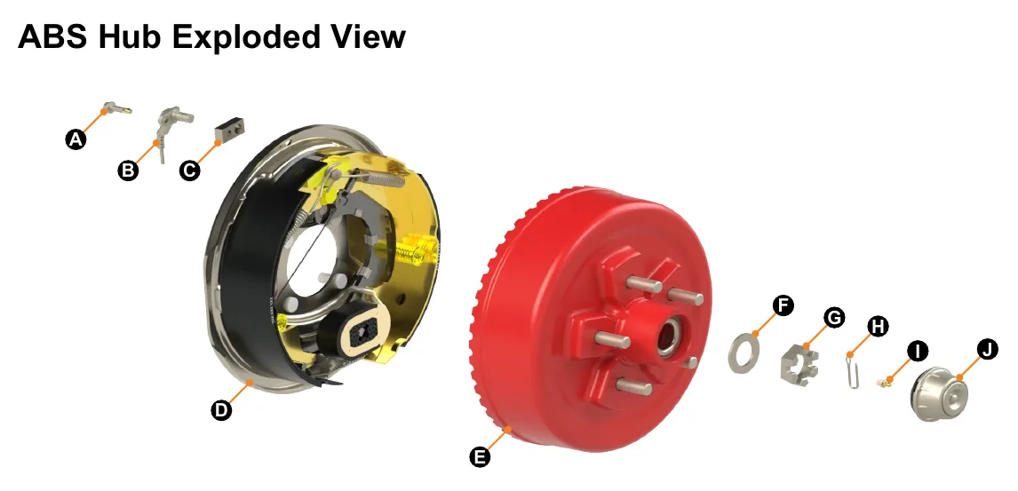
Confirm that the correct replacement parts are present before starting. The exploded view identifies the sensor, shims, brake, hub drum, spindle washer, castle nut, cotter pin, and dust cap, but is a general identification reference rather than a guarantee that every assembly is identical.
Lift and support the trailer according to its manufacturer's requirements, lifting by the frame rather than the axle or suspension. Remove the wheel and dust cap, discard the removed cotter pin, and remove the spindle nut and washer. Contain or remove the outer bearing cone while removing the hub; brake adjustment may need to be backed off.
For manual adjustment of the documented automatic-adjusting brakes, remove the backing-plate plug and expand the shoes with the starwheel until the wheel is very difficult to turn. Reverse the starwheel until rotation is free with slight lining drag, using another screwdriver to hold the automatic-adjusting lever away. Refit the plug and set all brakes to the same clearance.
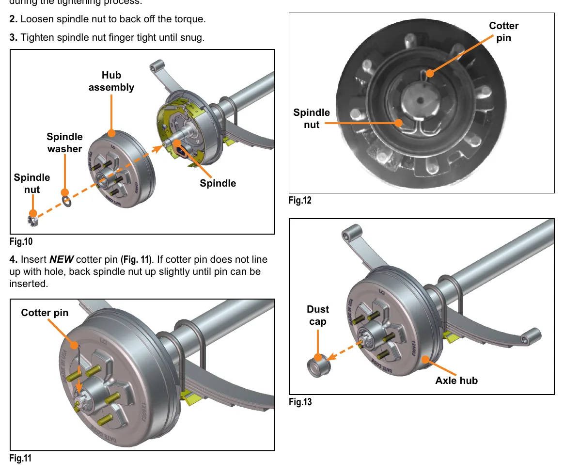
During replacement, install the hub, washer, and nut. Lippert specifies an initial spindle-nut torque of 50 ft-lb (68 Nm) while rotating the hub, followed by loosening and finger-tightening until snug; values vary by maker. Install a new cotter pin, backing the nut off slightly if needed for alignment, bend the pin, and seat the dust cap with a rubber mallet. The initial torque is not the final nut setting.
How It Works
Safe support and controlled disassembly
Verify replacement parts against the actual assembly because the exploded view is an identification reference, not a guarantee that every wheel end is identical. Lift by the frame and use suitable jack stands according to the manufacturer's requirements; never work under an unsupported trailer. Contain the outer bearing cone as the hub comes off, and back off brake adjustment if needed rather than forcing the drum over the shoes.
Bearing seating is not final adjustment
Lippert specifies an initial spindle-nut torque of 50 ft-lb (68 Nm) while rotating the hub, followed by loosening and finger-tightening until snug; values vary by maker. Rotation helps the bearing components settle during initial tightening, but leaving the nut at the initial torque can impose excessive bearing load and generate heat. Install a new cotter pin, backing the nut off slightly if alignment requires it, bend the pin, and seat the dust cap with a rubber mallet.
Mechanical shoe clearance
For manual adjustment of the documented automatic-adjusting brakes, remove the backing-plate plug and expand the shoes with the starwheel until the wheel is very difficult to turn. Hold the automatic-adjusting lever away with another screwdriver and reverse the starwheel until rotation is free with slight lining drag, then refit the plug and set all brakes to the same clearance. Excessive clearance delays shoe contact, while insufficient clearance promotes continuous friction and heat; clear people and vehicles from the area before testing or adjustment.
Step-by-Step Procedure
0/8 doneLippert hub-installation value; values vary by maker
| Initial spindle-nut tightening | 50 ft-lb (68 Nm) while rotating the hub; then loosen and finger-tighten until snug |
Figures
Diagnostic Chart
| Symptom | Check | Spec / Expected | Likely cause & fix |
|---|---|---|---|
| Hub resists removal after the spindle nut and washer are removed. | Check whether the shoes are holding the drum, and keep the outer bearing cone contained as the hub moves outward. | Brake adjustment may need to be backed off during hub removal. | The shoes may be preventing the drum from clearing the brake assembly. Basis: ccd-0011131 |
| Wheel remains very difficult to turn after manual brake adjustment. | Verify that the starwheel was reversed after expanding the shoes and that the automatic-adjusting lever was held away. | Final rotation must be free with slight lining drag; set all brakes to the same clearance and refit the backing-plate plug. | Adjustment may have stopped at the shoe-expansion stage, or the lever may have prevented backing off. Basis: ccd-0011131 |
| Spindle nut was left at the initial installation torque. | Identify the assembly manufacturer and verify that the loosening and finger-tightening stages were completed before fitting the cotter pin. | Lippert: 50 ft-lb (68 Nm) while rotating the hub; then loosen and finger-tighten until snug. Values vary by maker. | The initial bearing-seating torque was mistaken for the final nut setting. Basis: ccd-0011131 |
| Cotter pin will not pass through the spindle with the nut snug. | Check castle-nut alignment and confirm that a new cotter pin is available. | Back the nut off slightly if needed for alignment, install a new cotter pin, and bend the pin to retain the nut. | The nut slot and spindle hole are not aligned at the snug position. Basis: ccd-0011131 |
At the Bay: Diagnose the Case
CASE 1 / 4
Hub resists removal after the spindle nut and washer are removed.
- Test
- Compare
- Correct
Select the next check
Basis: ccd-0011131. A likely cause is a hypothesis; confirm it with the applicable service procedure before repair.
Common Bay Mistakes
- ✕ Treating the exploded view as proof that all replacement parts fit.
- ✕ Lifting by the axle or suspension, or relying on an unsupported trailer.
- ✕ Leaving the spindle nut at initial torque or reusing the removed cotter pin.
- ✕ Forgetting to hold the adjusting lever away or restore the backing-plate plug.
Quick Check
Practice only — not scored.
Plan the Service Sequence
Planning practice only. Follow the applicable manufacturer's instructions, employer safety program and qualified supervision on real equipment.
Plan the first action. Compare the service steps with the bay mistakes.
Hands-on: Shop Test Equipment
ABS Sensor Gap & Blink-Code Scanner
Non-magnetic feeler gauge, AC millivolt meter on the sensor, ECU blink-code button
🛠 Equip your bay for this test →Symptom: Post-repair verification.
Spec limits used
- 1.00–1.75 mm — Wheel-speed sensor air gap (Lippert ABS manual, p.13)
- 068Ah / 0006h — Sensor fault codes (Lippert ABS)
- illustrative only — Sensor AC output while spinning (General shop practice)
Simulated readings for practice. Always follow the manufacturer's procedure and values on a real trailer.
Source: ccd-0011131 — 3-7