Recognize ABS Electrical and Harness Basics
- Distinguish ordinary braking from active anti-lock control.
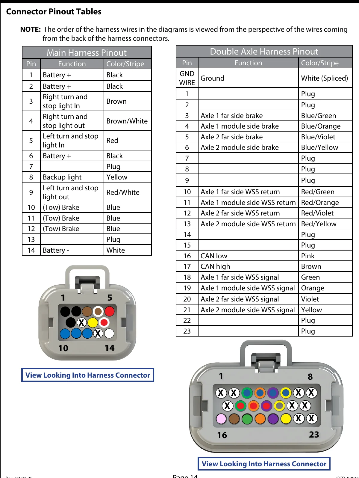
- Identify ABS harness functions and connector viewing orientation.
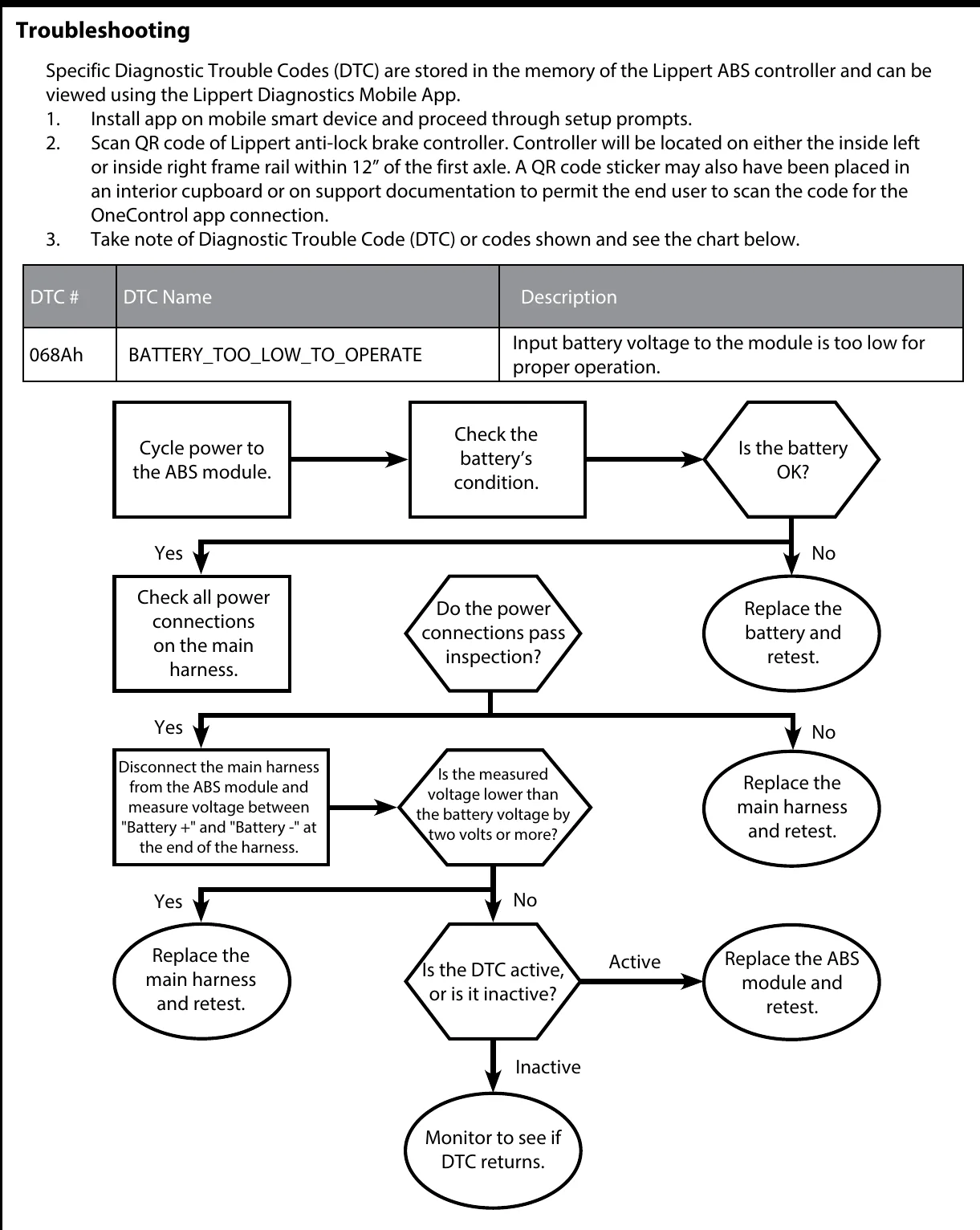
- Use diagnostic codes and prescribed power cycling to guide testing.
- Diagnostic application device — Run the specified diagnostic application and access the system using the controller QR code.
- Digital multimeter — Perform electrical checks directed by the matching diagnostic chart; never measure resistance on an energized circuit.
- Electrical test probes — Contact identified circuits without forcing connector terminals or damaging seals.
- Inspection light — Inspect harness routing, connector condition, and wheel-end wiring.
- Wheel chocks and trailer support stands — Secure and support the trailer according to the system safety instructions before working underneath.
In the documented ABS system, the driver brake command passes through the module when anti-lock control is inactive. When a wheel approaches lockup, the module temporarily reduces that wheel's braking below the driver command, then restores the command when the wheel is stable.
The source states that loss of module power or an active diagnostic trouble code leaves the brake outputs following the driver command, but disables anti-lock operation. Ordinary brake application therefore does not by itself confirm that ABS is functioning.
The main harness connects the module to power, ground, and the tow vehicle connection. The axle harness serves the wheel ends, and wheel speed sensors monitor wheel rotation; the source also uses actuator as another term for a brake magnet.
Read diagnostic trouble codes with the specified diagnostic application and follow the chart for the reported fault. For pin identification, follow the source note that the harness-wire order is viewed from the wires entering the back of the connector, rather than assuming the tow vehicle receptacle perspective.
How It Works
Brake command and anti-lock intervention
In the documented system, the driver brake command passes through the module when anti-lock control is inactive. When a wheel approaches lockup, the module temporarily reduces that wheel's braking below the driver command and restores the command when the wheel becomes stable. This intervention helps prevent a sliding wheel from losing the traction needed for controlled braking.
Harness roles and connector orientation
The main harness connects the module to power, ground, and the tow vehicle connection, while the axle harness serves the wheel ends. Wheel speed sensors monitor wheel rotation; the source also calls a brake magnet an actuator. Identify harness circuits from the wires entering the back of the connector, because assuming the tow vehicle receptacle perspective can lead to testing the wrong circuit.
Fault codes do not prove total brake loss
The source states that loss of module power or an active diagnostic trouble code leaves brake outputs following the driver command but disables anti-lock operation. Ordinary brake application therefore does not prove that ABS is working. Record the displayed codes and read the matching diagnostic chart before testing or replacing components.
Step-by-Step Procedure
0/7 doneLippert ABS power-cycle interval; values vary by maker
| Wait after disconnecting all power sources | 10 seconds before reconnecting |
Figures
Diagnostic Chart
| Symptom | Check | Spec / Expected | Likely cause & fix |
|---|---|---|---|
| Ordinary brakes apply, but anti-lock operation is in doubt. | Access the system with the specified diagnostic application and controller QR code, record displayed codes, and follow the matching chart, including directed module-power checks. | Module power loss or an active diagnostic trouble code disables anti-lock operation while brake outputs follow the driver command. | Module power loss or an active fault may disable anti-lock control without eliminating ordinary brake application. Basis: Lippert-Anti-Lock-Braking-System |
| Circuit identification does not agree with the harness diagram. | Confirm that the connector is being viewed from the wires entering its back before locating or testing circuits. | Harness-wire order is viewed from the wires entering the back of the connector, not the assumed tow vehicle receptacle perspective. | Using the wrong viewing perspective can assign a circuit to the wrong terminal. Basis: Lippert-Anti-Lock-Braking-System |
| A prescribed power cycle appears not to reset the system. | Verify that every power source is disconnected, including tow-connector, shore, or solar power where present, then complete the prescribed wait before reconnecting. | 10 seconds before reconnecting | A remaining power source or an incomplete waiting interval can prevent completion of the prescribed power cycle. Basis: Lippert-Anti-Lock-Braking-System |
| An electrical fault appears intermittently. | With the trailer secured and electrical testing made safe, inspect wiring for chafing, loose terminal retention, corrosion, and strain near connectors; follow the applicable fault chart for testing. | Use the applicable manufacturer's diagnostic criteria; no universal electrical limit is supplied here. | Vibration can interrupt a loose connection, corrosion can increase resistance, and damaged insulation can permit unintended circuit contact. Basis: General shop practice |
At the Bay: Diagnose the Case
CASE 1 / 4
Ordinary brakes apply, but anti-lock operation is in doubt.
- Test
- Compare
- Correct
Select the next check
Basis: Lippert-Anti-Lock-Braking-System. A likely cause is a hypothesis; confirm it with the applicable service procedure before repair.
Common Bay Mistakes
- ✕ Treating ordinary brake application as proof of functioning ABS.
- ✕ Replacing a component from a code alone without reading its diagnostic chart.
- ✕ Locating harness pins from the wrong connector viewing perspective.
- ✕ Leaving a power source connected during a prescribed power cycle.
Quick Check
Practice only — not scored.
Plan the Service Sequence
Planning practice only. Follow the applicable manufacturer's instructions, employer safety program and qualified supervision on real equipment.
Plan the first action. Compare the service steps with the bay mistakes.
Hands-on: Test Bench Practice
Symptom: Healthy trailer. Learn what good readings look like.
Tap a point to place the red probe.
Good system: ~12.6 V at pins, 3.2 Ω across a 12×2-inch magnet (unplugged), 3.0 A per magnet at 12 V full gain, and at least 10.5 V at the magnet — the chart values from the axle manuals.
Hands-on: Shop Test Equipment
IPA #9107B Electric Brake Force Meter
Plugs into the truck's 7-way socket on a 25 ft cable; simulates a trailer load and shows controller output on 10 blue LEDs
🛠 Equip your bay for this test →Symptom: Customer wants the truck checked before buying a trailer.
Spec limits used
- 1–10, each 1.0–1.5 V — Gain LEDs (IPA #9107B manual, p.5)
- 15 s — Max time holding brake pedal (IPA #9107B manual, p.4)
- set-up step 5 — Connect the 9-pin only after the engine is running (IPA #9107B manual, p.3)
- hold brake pedal during ECU detection — 2016–2017 'Trailer Connected' not shown (IPA #9107B manual, p.3)
- faulty brake control module or relay — ECU light never lights on a vehicle with a controller (IPA #9107B manual, p.5)
Simulated readings for practice. Always follow the manufacturer's procedure and values on a real trailer.
Hands-on: Wire-Trace Overlay
Pin 2 · Blue
Electric brakes
- Left and right brake magnets
- Breakaway switch output
Check points
- Two brakes draw about 6.0 A (3.0 A per magnet) at 12 V full gain.
- Unplugged: 3.2 Ω per magnet; at least 10.5 V at each magnet under load.
Common failures
- Open magnet: about half the expected current and a pull to one side.
- Shorted magnet: very low resistance and controller overload.
- Wire chafed where it drops to the axle.
Colors shown are the most common RV harness colors; makers vary — always verify against the trailer's wiring diagram.
Source: Lippert-Anti-Lock-Braking-System — 2-4, 14-15