Trace the Electrical Command and Hydraulic Braking Action
- Trace the electrical command through the actuator to hydraulic brake application.
- Distinguish floating-caliper movement from fixed-caliper piston action.
- Verify controller compatibility and application-specific pressure limits.
- Inspection light — Locate actuator identification, hydraulic connections, caliper pistons, and sliding features.
- Inspection mirror — View obscured caliper features and identification markings without assuming the caliper design.
- Digital multimeter — Check actuator power, ground, and command circuits according to the applicable wiring and test procedures.
- Hydraulic brake pressure test kit — Measure actuator output using compatible fittings and equipment rated for the installed system.
- Wheel chocks — Secure the trailer against movement before inspection or controlled brake testing.
An electric-over-hydraulic system uses an electronic braking command to control hydraulic brake application. The actuator described in the source contains electronics, a high-pressure piston pump, and a proportioning valve, and supplies pressurized fluid in proportion to the braking effort requested through tow-vehicle deceleration.
Controller compatibility must be established rather than assumed. The source assigns that responsibility to the end user because controller manufacturers can change their designs. A controller that operates another type of trailer brake is not automatically established as compatible with the hydraulic actuator.
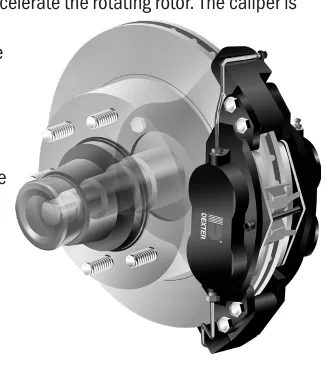
Both disc-brake designs press friction pads against a ventilated rotor attached to the hub. Friction converts motion into heat, and the ventilated rotor dissipates that heat. In a floating caliper, pistons on the inboard side apply the inner pad and lateral caliper movement applies the outer pad with equivalent force.
A fixed caliper has pistons on both sides of the rotor and remains stationary during application. Its pistons and internal seals maintain pad clearance as the linings wear; the floating design also maintains clearance automatically. Disc braking effectiveness is the same in forward and reverse travel. Dexter specifies a maximum operating pressure of 1,600 psi for the disc brakes covered here; values vary by maker and application.
How It Works
Follow the command before judging the brake
The electronic braking command directs the actuator electronics, high-pressure piston pump, and proportioning valve to supply fluid pressure proportional to the requested braking effort. Controller compatibility must be confirmed for the installed actuator because controller designs can change, and operation of another brake type does not establish compatibility.
Recognize how each caliper applies its pads
A floating caliper uses inboard pistons to apply the inner pad, while lateral caliper movement applies the outer pad with equivalent force. A fixed caliper remains stationary and uses pistons on both sides of the rotor; both designs automatically maintain pad clearance as linings wear. Restricted sliding movement can therefore impair a floating caliper even when hydraulic pressure reaches it.
Separate heat conversion from pressure selection
Both designs clamp pads against a ventilated rotor attached to the hub, converting motion into heat that the rotor dissipates, and disc braking effectiveness is the same in forward and reverse travel. The covered Dexter disc brakes have a maximum operating pressure of 1,600 psi, and the E/H 1600 disc-brake actuator has a maximum output of 1,600 psi. The E/H 1000 drum-brake actuator output is 1,000 psi; these are application-specific examples, not interchangeable service specifications.
Step-by-Step Procedure
0/6 doneDexter examples only; values vary by maker and application
| Covered hydraulic disc brakes: maximum operating pressure | 1,600 psi |
| E/H 1000 drum-brake actuator output | 1,000 psi |
| E/H 1600 disc-brake actuator maximum output | 1,600 psi |
Figures
Diagnostic Chart
| Symptom | Check | Spec / Expected | Likely cause & fix |
|---|---|---|---|
| The hydraulic actuator does not respond properly to the tow-vehicle controller. | Identify the installed controller and actuator, establish compatibility, and trace the electronic command to the actuator before condemning a hydraulic component. | Compatibility must be established for the installed controller and hydraulic actuator. | Controller incompatibility may prevent correct actuator operation even if the controller operates another brake type. Basis: LDServiceOnline |
| A floating caliper shows uneven pad wear or poor outer-pad application. | With the trailer safely secured and the brake released, inspect sliding features for corrosion, binding, or damage using the applicable service procedure. | Use the installed caliper manufacturer's movement and wear criteria. | Restricted lateral movement can prevent the caliper from transferring clamping action effectively to the outer pad. Basis: General shop practice |
| The caliper body remains stationary during brake application. | Identify piston locations and determine whether the caliper is fixed or floating before treating the lack of body movement as a fault. | Fixed calipers remain stationary and have pistons on both sides; floating calipers move laterally and have inboard pistons. | Normal fixed-caliper operation may be mistaken for a seized floating caliper. Basis: LDServiceOnline |
| Pressure readings are being judged against a drum-brake actuator specification on a disc-brake trailer. | Identify the wheel-brake design and actuator model, then compare measured pressure with the applicable brake and actuator information. | Covered Dexter disc brakes: maximum operating pressure 1,600 psi. E/H 1600: maximum output 1,600 psi. E/H 1000 drum-brake actuator: output 1,000 psi. | Selecting service information by appearance or familiarity can lead to an incorrect pressure comparison. Basis: LDServiceOnline |
At the Bay: Diagnose the Case
CASE 1 / 4
The hydraulic actuator does not respond properly to the tow-vehicle controller.
- Test
- Compare
- Correct
Select the next check
Basis: LDServiceOnline. A likely cause is a hypothesis; confirm it with the applicable service procedure before repair.
Common Bay Mistakes
- ✕ Assuming a controller is compatible because it operates another brake type.
- ✕ Applying a drum-brake pressure specification to a disc-brake installation.
- ✕ Calling a stationary caliper seized before identifying its design.
- ✕ Treating maximum pressure as the required pressure at every braking command.
Quick Check
Practice only — not scored.
Plan the Service Sequence
Planning practice only. Follow the applicable manufacturer's instructions, employer safety program and qualified supervision on real equipment.
Plan the first action. Compare the service steps with the bay mistakes.
Hands-on: Test Bench Practice
Symptom: Healthy trailer. Learn what good readings look like.
Tap a point to place the red probe.
Good system: ~12.6 V at pins, 3.2 Ω across a 12×2-inch magnet (unplugged), 3.0 A per magnet at 12 V full gain, and at least 10.5 V at the magnet — the chart values from the axle manuals.
Hands-on: Shop Test Equipment
Hydraulic Pressure & Relief Gauge
0–5,000 psi gauge on the pump pressure port, DC clamp meter, battery voltmeter
🛠 Equip your bay for this test →Symptom: Routine check before a customer pickup.
Spec limits used
- 3,200 psi — Primary relief (factory preset) (KTI Hydraulics Troubleshooting Manual 2019)
- 1,500 psi — Secondary relief, circuit 111 (KTI Hydraulics Troubleshooting Manual 2019)
- below 9 V — Low-voltage alarm (KTI remote)
- illustrative only — Motor current & voltage drop (General shop practice)
Simulated readings for practice. Always follow the manufacturer's procedure and values on a real trailer.
Source: LDServiceOnline — 24-29