Control Fixed-Caliper Line Routing and Production Differences
- Select the correct production-specific inlet and bleeder layout.
- Route and support hydraulic lines without rotor or wheel interference.
- Apply connection-specific torque and verify completed assembly clearance.
- Flare-nut wrenches — Tighten hydraulic line fittings while reducing the risk of rounding their flats.
- Foot-pound torque wrench and sockets — Tighten covered caliper mounting bolts to the applicable specification.
- Inch-pound torque wrench and suitable adapters — Tighten specified bleeder, adapter, union, and support-bracket fasteners using the correct units.
- Inspection light and mirror — Inspect bleeder orientation, crossover routing, bracket placement, and hidden clearance points.
- Bleeder hose and collection container — Collect discharged fluid during bleeding and flushing performed according to the actuator manual.
- Jack and rated support stands — Support the trailer safely for assembly access and rotor or wheel rotation checks.
Fixed-caliper replacement includes hydraulic-line routing as well as mechanical attachment. The installation description initially places the hydraulic fitting adapter on the inboard caliper and an upward-pointing bleeder on the outboard caliper. It then describes a later arrangement with the bleeder on the inboard caliper, so the initial layout must not be treated as universal.
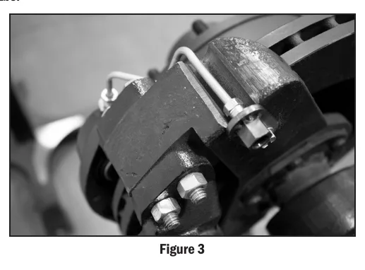
The crossover line connects the bottom sides of the caliper piston bosses. It must fit closely around the assembly without touching the rotor. Spin the rotor to verify clearance rather than relying only on the appearance of a stationary assembly.
Dexter identifies an arrangement produced after June 2018 with a remote inlet line entering the top of the outboard caliper and the bleeder on the inboard caliper. Its line union and bracket are supported at the anchor yoke. The same source gives 25–35 ft-lb for the covered caliper mounting bolts, 12–15 ft-lb for the specified line connections, and 60–76 in-lb for the specified bleeder and adapter fittings; values vary by maker.
Reassemble pads with their linings toward the rotor and steel backing toward the calipers, using the applicable retaining-hardware arrangement. Reconnect actuation and bleed and flush according to the actuator manual. After wheel installation, spin the wheel to confirm clearance from the crossover line and caliper.
How It Works
Production layout determines component placement
The initial installation description places the hydraulic fitting adapter on the inboard caliper and an upward-pointing bleeder on the outboard caliper; that arrangement is not universal. Dexter identifies an arrangement produced after June 2018 with the remote inlet entering the top of the outboard caliper, the bleeder on the inboard caliper, and the line union and bracket supported at the anchor yoke. Keep the bleeder upward in the location specified for the applicable arrangement because trapped air rises and can prevent a firm hydraulic response.
Clearance and support protect the hydraulic circuit
The crossover line connects the bottom sides of the caliper piston bosses and must fit closely around the assembly without touching the rotor. Contact can abrade the tube, while unsupported movement can fatigue tubing and stress fittings. Spin the rotor after routing, then spin the installed wheel to check clearance from both the crossover line and caliper.
Torque and final assembly are connection-specific
For the covered Dexter installation, caliper mounting bolts use 25–35 ft-lb, while the crossover line and specified remote inlet connection use 12–15 ft-lb. The bleeder screw, hydraulic fitting adapter, and specified line union use 60–76 in-lb, while the specified line-support bracket bolt uses 85–100 in-lb; these values vary by maker and must not be transferred indiscriminately. Reinstall pads with linings toward the rotor and steel backing toward the calipers, fit the applicable retaining hardware, and reconnect actuation before bleeding and flushing according to the actuator manual.
Step-by-Step Procedure
0/8 doneDexter covered fixed-caliper installation values; values vary by maker
| Caliper mounting bolts | 25–35 ft-lb |
| Crossover line and specified remote inlet connection | 12–15 ft-lb |
| Bleeder screw, hydraulic fitting adapter, and specified line union | 60–76 in-lb |
| Specified line-support bracket bolt | 85–100 in-lb |
Figures
Diagnostic Chart
| Symptom | Check | Spec / Expected | Likely cause & fix |
|---|---|---|---|
| Bleeder and inlet placement do not match the replacement assembly. | Identify the applicable production arrangement before moving fittings; compare inlet entry, bleeder location, and support placement with its installation description. | The arrangement produced after June 2018 has a remote inlet entering the top of the outboard caliper, an upward bleeder on the inboard caliper, and union and bracket support at the anchor yoke. | The initial outboard-bleeder layout may have been applied to the later remote-inlet arrangement. Basis: LDServiceOnline |
| Crossover line shows rubbing or clearance appears doubtful. | Inspect routing around the bottom piston bosses and spin the rotor; after wheel installation, spin the wheel and inspect line and caliper clearance. | The crossover line must fit closely without touching the rotor, and the installed wheel must clear the crossover line and caliper. | The crossover may be incorrectly positioned, or clearance may have been judged only with the assembly stationary. Basis: LDServiceOnline |
| A remote inlet union or support bracket is loose after assembly. | Verify anchor-yoke support placement and identify each connection before checking its specified torque and units. | Covered Dexter specified line union: 60–76 in-lb; specified line-support bracket bolt: 85–100 in-lb; crossover line and specified remote inlet connection: 12–15 ft-lb. | Support hardware may be omitted or misplaced, or torque values may have been assigned to the wrong connection. Basis: LDServiceOnline |
| Fluid appears around a hydraulic connection after reconnection. | Clean and dry the connection, inspect the tube and fitting for damage or misalignment, and observe for renewed leakage during a controlled actuation check. Do not return the trailer to service with an unresolved leak. | A hydraulic connection must remain leak-free; verify its applicable assembly requirements before correction. | A damaged sealing surface, cross-threaded fitting, or tubing strain may prevent sealing; additional tightening alone may worsen the damage. Basis: General shop practice |
At the Bay: Diagnose the Case
CASE 1 / 4
Bleeder and inlet placement do not match the replacement assembly.
- Test
- Compare
- Correct
Select the next check
Basis: LDServiceOnline. A likely cause is a hypothesis; confirm it with the applicable service procedure before repair.
Common Bay Mistakes
- ✕ Treating the initial outboard-bleeder location as universal.
- ✕ Confusing inch-pounds with foot-pounds.
- ✕ Accepting stationary appearance instead of checking rotating clearance.
- ✕ Installing pads with steel backing toward the rotor.
Quick Check
Practice only — not scored.
Plan the Service Sequence
Planning practice only. Follow the applicable manufacturer's instructions, employer safety program and qualified supervision on real equipment.
Plan the first action. Compare the service steps with the bay mistakes.
Hands-on: Test Bench Practice
Symptom: Healthy trailer. Learn what good readings look like.
Tap a point to place the red probe.
Good system: ~12.6 V at pins, 3.2 Ω across a 12×2-inch magnet (unplugged), 3.0 A per magnet at 12 V full gain, and at least 10.5 V at the magnet — the chart values from the axle manuals.
Hands-on: Shop Test Equipment
Hydraulic Pressure & Relief Gauge
0–5,000 psi gauge on the pump pressure port, DC clamp meter, battery voltmeter
🛠 Equip your bay for this test →Symptom: Routine check before a customer pickup.
Spec limits used
- 3,200 psi — Primary relief (factory preset) (KTI Hydraulics Troubleshooting Manual 2019)
- 1,500 psi — Secondary relief, circuit 111 (KTI Hydraulics Troubleshooting Manual 2019)
- below 9 V — Low-voltage alarm (KTI remote)
- illustrative only — Motor current & voltage drop (General shop practice)
Simulated readings for practice. Always follow the manufacturer's procedure and values on a real trailer.
Source: LDServiceOnline — 44-46