Circuit Layout and Wire Selection
- Identify connector connections using the correct drawing viewpoint.
- Trace brake operation from controller current to shoe movement.
- Select minimum copper wire size from the applicable equipment chart.
- Digital multimeter — Check supply voltage and loaded voltage drop; check continuity only with the circuit isolated and de-energized.
- DC clamp ammeter — Observe brake current around an individual conductor while the controller commands braking.
- Tape measure — Determine the hitch-to-axle distance used by the applicable wire-selection chart.
- Inspection light — Read connector markings and inspect terminals, wire identification, and accessible harness sections.
- Electrical test leads with back-probe adapters — Access suitable test points without spreading connector terminals or unnecessarily piercing insulation.
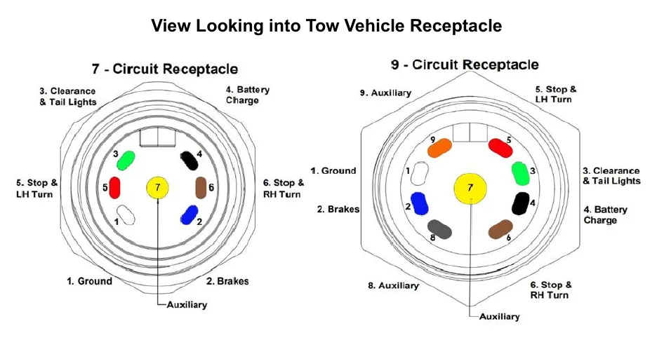
Begin by identifying the trailer electrical connector and its wiring orientation from the applicable diagram. The connector links the tow vehicle to the trailer, but connector arrangements must be checked against the trailer manufacturer's information. Read the viewpoint stated on a receptacle drawing before using it to identify connections.
Understand the electrical-to-mechanical sequence before tracing a brake complaint. The controller supplies current to the brake electromagnets, which engage the rotating drum armature surfaces. Magnet movement operates the actuating levers, and the resulting shoe movement produces braking.
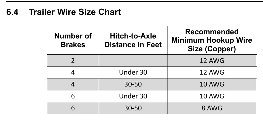
Increasing magnet current increases its grip on the armature and the pressure applied through the shoes. Consequently, a wiring assessment must consider whether the circuit can deliver the required current, not merely whether the connector has been identified. The source's hookup chart selects minimum copper wire size using brake count and hitch-to-axle distance.
Use the chart that applies to the actual equipment rather than treating one manufacturer's recommendation as universal. For example, Bostail specifies 12 AWG copper for four brakes under 30 feet, 10 AWG for four brakes at 30–50 feet, and 8 AWG for six brakes at 30–50 feet. Values vary by maker; confirm the applicable trailer documentation before selecting wiring.
How It Works
Connector identity includes viewpoint
Identify the connector from the applicable diagram and confirm whether the drawing shows the mating face or the wire-entry side before assigning connections. Viewing the connector from the opposite side can reverse apparent terminal locations, so physical resemblance alone is not sufficient evidence of correct wiring. Use the trailer manufacturer's connector information to establish the actual arrangement.
Current must produce mechanical braking
The controller supplies current to the electromagnets, which grip the rotating drum armature surfaces and move the actuating levers to apply the shoes. Increasing magnet current increases grip and shoe pressure, while circuit resistance can reduce the current available under load. Electrical and mechanical checks therefore belong in the same diagnostic sequence; neither the trailer brakes nor the tow vehicle brakes alone should be relied on to stop the combined load.
Wire selection depends on the equipment
The applicable hookup chart selects minimum copper wire size using brake count and hitch-to-axle distance because conductor resistance and circuit demand affect current delivery. Bostail examples specify 12 AWG minimum for four brakes under 30 feet, 10 AWG minimum for four brakes at 30–50 feet, and 8 AWG minimum for six brakes at 30–50 feet. These are manufacturer-specific examples, not universal wiring recommendations.
Step-by-Step Procedure
0/6 doneBostail copper hookup examples; values vary by maker
| Four brakes, under 30 ft | 12 AWG minimum |
| Four brakes, 30–50 ft | 10 AWG minimum |
| Six brakes, 30–50 ft | 8 AWG minimum |
Figures
Diagnostic Chart
| Symptom | Check | Spec / Expected | Likely cause & fix |
|---|---|---|---|
| Connector connections do not agree with the expected circuit functions. | Identify the connector, read the drawing's stated viewpoint, and compare terminal assignments with the trailer manufacturer's information before moving wires. | Use the applicable connector diagram and its stated viewing direction. | The connector may have been identified from the wrong viewpoint or an inapplicable diagram. Basis: Bostail 8K Axle Manual |
| Brakes remain weak despite apparent electrical continuity. | With the trailer secured and braking commanded, check voltage drop across accessible supply and return sections and inspect suspect connections. Do not treat an unloaded continuity result as proof of adequate current delivery. | Evaluate loaded measurements against applicable equipment service information; no electrical test limit is supplied here. | Corrosion, loose terminals, or damaged conductors can pass a continuity check yet restrict operating current. Basis: General shop practice |
| Installed hookup wire may be too small for the brake installation. | Confirm the brake count, measure hitch-to-axle distance, identify conductor material and size, and match the installation to the applicable manufacturer's chart. | Bostail examples: four brakes under 30 feet require 12 AWG minimum; four brakes at 30–50 feet require 10 AWG minimum; six brakes at 30–50 feet require 8 AWG minimum. | Wire may have been selected without accounting for brake count, distance, or the correct manufacturer's requirements. Basis: Bostail 8K Axle Manual |
| Electrical response is present, but shoe application remains ineffective. | Trace the operating sequence through magnet engagement with the rotating armature, actuating-lever movement, and resulting shoe movement. | Controller current must lead to magnet engagement, lever operation, and shoe movement. | The electrical-to-mechanical sequence may be interrupted after current reaches the magnet. Basis: Bostail 8K Axle Manual |
At the Bay: Diagnose the Case
CASE 1 / 4
Connector connections do not agree with the expected circuit functions.
- Test
- Compare
- Correct
Select the next check
Basis: Bostail 8K Axle Manual. A likely cause is a hypothesis; confirm it with the applicable service procedure before repair.
Common Bay Mistakes
- ✕ Assigning terminals without confirming the drawing viewpoint.
- ✕ Treating continuity as proof of loaded circuit performance.
- ✕ Applying Bostail wire examples to every manufacturer's equipment.
- ✕ Relying on either braking system alone to stop the combined load.
Quick Check
Practice only — not scored.
Plan the Service Sequence
Planning practice only. Follow the applicable manufacturer's instructions, employer safety program and qualified supervision on real equipment.
Plan the first action. Compare the service steps with the bay mistakes.
Hands-on: Test Bench Practice
Symptom: Healthy trailer. Learn what good readings look like.
Tap a point to place the red probe.
Good system: ~12.6 V at pins, 3.2 Ω across a 12×2-inch magnet (unplugged), 3.0 A per magnet at 12 V full gain, and at least 10.5 V at the magnet — the chart values from the axle manuals.
Hands-on: Shop Test Equipment
IPA #9107B Electric Brake Force Meter
Plugs into the truck's 7-way socket on a 25 ft cable; simulates a trailer load and shows controller output on 10 blue LEDs
🛠 Equip your bay for this test →Symptom: Customer wants the truck checked before buying a trailer.
Spec limits used
- 1–10, each 1.0–1.5 V — Gain LEDs (IPA #9107B manual, p.5)
- 15 s — Max time holding brake pedal (IPA #9107B manual, p.4)
- set-up step 5 — Connect the 9-pin only after the engine is running (IPA #9107B manual, p.3)
- hold brake pedal during ECU detection — 2016–2017 'Trailer Connected' not shown (IPA #9107B manual, p.3)
- faulty brake control module or relay — ECU light never lights on a vehicle with a controller (IPA #9107B manual, p.5)
Simulated readings for practice. Always follow the manufacturer's procedure and values on a real trailer.
Hands-on: Wire-Trace Overlay
Pin 2 · Blue
Electric brakes
- Left and right brake magnets
- Breakaway switch output
Check points
- Two brakes draw about 6.0 A (3.0 A per magnet) at 12 V full gain.
- Unplugged: 3.2 Ω per magnet; at least 10.5 V at each magnet under load.
Common failures
- Open magnet: about half the expected current and a pull to one side.
- Shorted magnet: very low resistance and controller overload.
- Wire chafed where it drops to the axle.
Colors shown are the most common RV harness colors; makers vary — always verify against the trailer's wiring diagram.
Source: Bostail 8K Axle Manual — 14-19