Electrical Operation and Evidence-Based Diagnosis
- Trace magnet actuation into brake shoe force.
- Measure brake voltage and current safely under specified conditions.
- Use isolation tests to distinguish controller, wiring, and magnet faults.
- Digital voltmeter — Measure voltage across the magnet leads with the tow vehicle engine running and observe controller output modulation.
- Suitably rated ammeter — Measure system current in series at the controller brake-output wire and individual current in series at a magnet lead, observing polarity.
- Inspection light — Examine connectors, grounds, exposed conductors, and visible brake components for damage or deterioration.
- Wire stripper and crimping tool — Repair disturbed wiring with appropriate terminals and sealed connections after testing.
- Heat gun — Seal compatible heat-shrink wiring repairs before returning the brakes to service.
Electric drum brakes convert electrical input into mechanical shoe force. The energized magnet contacts the rotating drum armature and moves the actuating lever with drum rotation. The lever pushes the primary shoe outward, and force passes through the adjuster to the secondary shoe. Increasing magnet current increases braking force; electrical supply and mechanical condition therefore both matter.
Begin electrical troubleshooting at the controller after considering brake adjustment and synchronization. Follow the controller manufacturer's testing instructions rather than assuming that harsh braking means the shoes alone are defective. Poor connections, open or broken wires, inadequate wire size, and controller faults can reduce voltage or current. Shorted coils or exposed conductors contacting ground can produce excessive current.
Measure voltage across the magnet leads with the tow vehicle engine running. Evaluate whether controller output increases progressively rather than immediately applying high output. For system current, place a suitably rated ammeter in series with the controller brake-output wire, observing polarity. For individual current, insert the ammeter in series at a magnet lead. Restore and seal connections after testing.
Interpret readings under the specified test conditions. Bostail lists at least 10.5 volts at each magnet when controller output is 12 volts, and its nominal current table assumes warm magnets, maximum controller gain, and the system resistor at zero. These values vary by maker and application. A high current reading that disappears when the trailer is unplugged locates the short on the trailer side; a high reading that remains with all magnets disconnected points to trailer wiring.
How It Works
Electrical input becomes mechanical force
The energized magnet contacts the rotating drum armature, and drum rotation moves the actuating lever. The lever pushes the primary shoe outward, transferring force through the adjuster to the secondary shoe. Increasing magnet current increases braking force, but worn linings, seized components, or poor adjustment can prevent adequate electrical input from producing effective braking.
Voltage and current answer different questions
Voltage across the magnet leads shows the electrical supply available to the magnet, while a series current measurement shows the current actually flowing through the tested circuit. Poor connections, broken wires, inadequate wire size, and controller faults can reduce voltage or current; shorted coils or exposed conductors contacting ground can produce excessive current. Consider mechanical condition, adjustment, and synchronization before beginning electrical troubleshooting at the controller.
Test conditions make readings meaningful
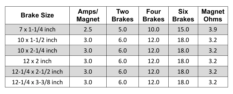
Bostail specifies at least 10.5 volts at each magnet when controller output is 12 volts, with voltage measured across the magnet leads while the tow vehicle engine is running. For a 12 × 2-inch brake, its nominal current is 3.0 amperes per magnet at 12 volts, with warm magnets, maximum gain, and system resistor at zero. These reference values vary by maker and application, so verify applicability before condemning a component.
Step-by-Step Procedure
0/7 doneBostail Electrical Reference Values — Values Vary by Maker
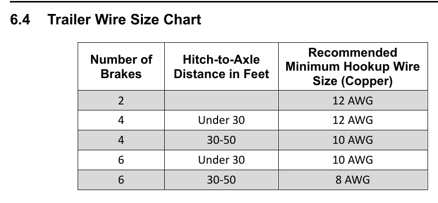
| Four brakes, hitch-to-axle distance 30–50 feet | Minimum copper hookup wire: 10 AWG. |
| Six brakes, hitch-to-axle distance 30–50 feet | Minimum copper hookup wire: 8 AWG. |
| Magnet voltage with 12 volts at controller | Minimum 10.5 volts at each magnet. |
| 12 × 2-inch brake nominal current | 3.0 amperes per magnet at 12 volts, with warm magnets, maximum gain, and system resistor at zero. |
Figures
Diagnostic Chart
| Symptom | Check | Spec / Expected | Likely cause & fix |
|---|---|---|---|
| Brakes apply harshly or abruptly. | Inspect for bent parts, worn linings, seized components, and loose hardware; consider adjustment and synchronization. Follow the controller manufacturer's test procedure and observe whether output increases progressively. | Controller output should increase progressively rather than immediately applying high output; use the controller manufacturer's testing instructions. | Incorrect controller adjustment, a controller fault, or mechanical problems can produce harsh braking; the symptom alone does not prove defective shoes. Basis: Bostail 8K Axle Manual |
| Braking is weak and magnet voltage is low. | With the tow vehicle engine running, measure across each magnet's leads. Inspect connector contact, grounds, wiring condition, and wire size against the applicable wiring chart. | Minimum 10.5 volts at each magnet with 12 volts at controller; confirm that the Bostail reference applies to the equipment. | Poor connections, open or broken wires, inadequate wire size, or controller faults can reduce the electrical supply reaching the magnets. Basis: Bostail 8K Axle Manual |
| Individual magnet current differs from the applicable nominal value. | Insert an adequately rated ammeter in series at a magnet lead, observing polarity. Confirm magnet temperature, supply voltage, controller gain, and resistor setting before comparing readings. | 12 × 2-inch brake nominal current: 3.0 amperes per magnet at 12 volts, with warm magnets, maximum gain, and system resistor at zero. | Low current can reflect inadequate supply or an interrupted circuit; excessive current can reflect a shorted coil or a conductor contacting ground. Basis: Bostail 8K Axle Manual |
| Total brake current is excessive. | Measure current in series at the controller brake-output wire using an adequately rated ammeter. Observe whether the excessive reading disappears when the trailer is unplugged, then isolate the magnets as needed. | A high reading that disappears when the trailer is unplugged locates the short on the trailer side; a high reading that remains with all magnets disconnected points to trailer wiring. | Shorted magnet coils or exposed conductors contacting ground can create excessive current; disconnection tests distinguish the affected circuit section. Basis: Bostail 8K Axle Manual |
At the Bay: Diagnose the Case
CASE 1 / 4
Brakes apply harshly or abruptly.
- Test
- Compare
- Correct
Select the next check
Basis: Bostail 8K Axle Manual. A likely cause is a hypothesis; confirm it with the applicable service procedure before repair.
Common Bay Mistakes
- ✕ Do not condemn shoes solely because braking is harsh.
- ✕ Never connect an ammeter across the supply as if measuring voltage.
- ✕ Do not apply nominal current values without matching their test conditions and application.
- ✕ Do not return the brakes to service with disturbed wiring left unsealed.
Quick Check
Practice only — not scored.
Plan the Service Sequence
Planning practice only. Follow the applicable manufacturer's instructions, employer safety program and qualified supervision on real equipment.
Plan the first action. Compare the service steps with the bay mistakes.
Hands-on: Test Bench Practice
Symptom: Healthy trailer. Learn what good readings look like.
Tap a point to place the red probe.
Good system: ~12.6 V at pins, 3.2 Ω across a 12×2-inch magnet (unplugged), 3.0 A per magnet at 12 V full gain, and at least 10.5 V at the magnet — the chart values from the axle manuals.
Hands-on: Shop Test Equipment
IPA #9107B Electric Brake Force Meter
Plugs into the truck's 7-way socket on a 25 ft cable; simulates a trailer load and shows controller output on 10 blue LEDs
🛠 Equip your bay for this test →Symptom: Customer wants the truck checked before buying a trailer.
Spec limits used
- 1–10, each 1.0–1.5 V — Gain LEDs (IPA #9107B manual, p.5)
- 15 s — Max time holding brake pedal (IPA #9107B manual, p.4)
- set-up step 5 — Connect the 9-pin only after the engine is running (IPA #9107B manual, p.3)
- hold brake pedal during ECU detection — 2016–2017 'Trailer Connected' not shown (IPA #9107B manual, p.3)
- faulty brake control module or relay — ECU light never lights on a vehicle with a controller (IPA #9107B manual, p.5)
Simulated readings for practice. Always follow the manufacturer's procedure and values on a real trailer.
Source: Bostail 8K Axle Manual — 14-47