Electrical Measurement and Fault Isolation
- Separate controller, wiring, magnet, and mechanical faults.
- Measure magnet voltage and brake current safely.
- Apply reference conditions and restore tested wiring.
- Digital multimeter — Measure voltage across magnet lead wires while the tow-vehicle engine runs and controller demand increases.
- Adequately rated series ammeter — Measure controller-output or individual-magnet current with correct polarity; verify capacity before connecting.
- Insulated hand tools — Open and restore controller-output and magnet connections without damaging terminals.
- Wire stripper and terminal crimper — Prepare damaged wire ends and make secure replacement connections when repairs are needed.
- Heat gun — Seal repaired connections using suitable heat-shrink materials.
Begin electrical troubleshooting at the controller and follow its manufacturer's testing instructions. Mechanical faults such as broken parts, seized components, and worn friction surfaces should also be considered rather than assuming every complaint is electrical.
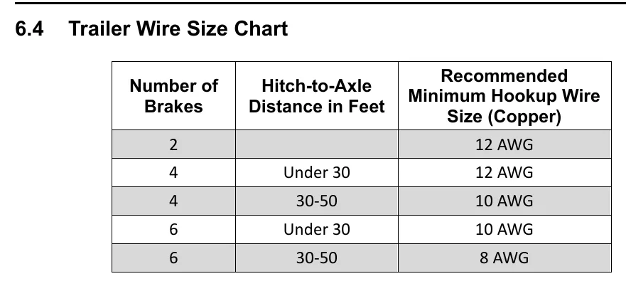
Wire selection depends on brake count and the specified wiring distance. Use the applicable chart instead of choosing wire only by connector appearance, and keep electrical connections sound because poor connections can cause low voltage and current at the brakes.
Measure magnet voltage across its lead wires with the tow-vehicle engine running so a low battery does not distort the result. Observe the output as the controller is gradually actuated; an immediate jump to high output indicates poor modulation rather than a smooth increase in braking demand.
Measure current with an ammeter in series, either at the controller brake-output wire or at an individual magnet. Use adequate meter capacity and correct polarity, compare results under the specified test conditions, and reconnect and seal disturbed wiring afterward. Abnormally high current suggests a short: unplugging the trailer and disconnecting magnets in turn help locate the affected section.
How It Works
Follow the circuit without ignoring the mechanism
Begin at the controller and follow its manufacturer's setup and testing instructions before working downstream through wiring and magnets. Electrical measurements identify supply and load problems, but broken parts, seized components, and worn friction surfaces can still cause poor braking when electrical operation appears normal.
Voltage loss and controller modulation
Wire selection must account for brake count and the chart's specified wiring distance because conductor resistance and poor connections can reduce voltage and current at the brakes. Measure voltage across the magnet leads with the tow-vehicle engine running, then gradually actuate the controller and watch for a smooth increase rather than an immediate jump to high output. The lesson reference calls for at least 10.5 V at each magnet with 12 V at the controller output; values vary by maker.
Current measures the connected load
An ammeter goes in series so brake-circuit current passes through it; connecting it across the supply can create a short and damage the meter or wiring. Compare current only under the stated conditions, since magnet temperature, controller gain, and system resistance affect the reading. Excessive current suggests a short, so isolate the trailer and then disconnect magnets in turn to locate the affected section before restoring and sealing every disturbed connection.
Step-by-Step Procedure
0/8 doneBostail electrical references; values vary by maker
| Four brakes, 30–50 ft hitch-to-axle distance | 10 AWG minimum copper hookup wire |
| Six brakes, 30–50 ft hitch-to-axle distance | 8 AWG minimum copper hookup wire |
| Magnet voltage comparison | At least 10.5 V at each magnet with 12 V at the controller output |
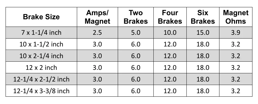
| Four 12 × 2 in brakes | 12.0 A nominal total at 12 V, warm magnets, zero system resistance setting, and maximum controller gain |
Figures
Interactive Demonstration
Planning practice only. Follow the applicable manufacturer's instructions, employer safety program and qualified supervision on real equipment.
Plan the first action. Compare the service steps with the bay mistakes.
Diagnostic Chart
| Symptom | Check | Spec / Expected | Likely cause & fix |
|---|---|---|---|
| Weak braking with low voltage at the magnets | Begin with the controller manufacturer's test procedure, then measure across each magnet's leads with the engine running. Inspect connections and verify wire size against brake count and hitch-to-axle distance. | At least 10.5 V at each magnet with 12 V at the controller output. Four brakes, 30–50 ft hitch-to-axle distance: 10 AWG minimum copper hookup wire. Six brakes, 30–50 ft hitch-to-axle distance: 8 AWG minimum copper hookup wire. | Poor connections, unsuitable wire size, or inadequate controller output can reduce voltage and current at the brakes. Basis: Bostail 8K Axle Manual |
| Brakes apply abruptly as controller demand begins | With the engine running, monitor voltage across the magnet leads while gradually actuating the controller. Check controller setup and operation against its manufacturer's instructions. | Output should increase smoothly; an immediate jump to high output indicates poor modulation. | Poor controller modulation can produce an abrupt increase in braking demand. Basis: Bostail 8K Axle Manual |
| System current is abnormally high | Insert an adequately rated ammeter in series at the disconnected blue controller output wire with correct polarity. Apply the specified comparison conditions, then unplug the trailer and disconnect magnets in turn to isolate the affected section. | Four 12 × 2 in brakes: 12.0 A nominal total at 12 V, warm magnets, zero system resistance setting, and maximum controller gain. Set any system resistor to zero or bypass it only as the source directs. | A short in wiring or a magnet circuit may draw excessive current; isolation distinguishes the affected section from other possible sources. Basis: Bostail 8K Axle Manual |
| Poor braking remains despite acceptable electrical results | Inspect brake components for broken parts, seizure, and worn friction surfaces rather than continuing to assume an electrical fault. | Consider mechanical faults alongside controller, wiring, and magnet faults. | Mechanical damage, restricted movement, or worn friction surfaces can prevent electrical demand from producing effective braking. Basis: Bostail 8K Axle Manual |
At the Bay: Diagnose the Case
CASE 1 / 4
Weak braking with low voltage at the magnets
- Test
- Compare
- Correct
Select the next check
Basis: Bostail 8K Axle Manual. A likely cause is a hypothesis; confirm it with the applicable service procedure before repair.
Common Bay Mistakes
- ✕ Choosing wire by connector appearance instead of the applicable chart.
- ✕ Comparing current without matching the stated test conditions.
- ✕ Connecting an ammeter across the supply instead of in series.
- ✕ Leaving disturbed brake wiring disconnected or unsealed.
Quick Check
Practice only — not scored.
Plan the Service Sequence
Planning practice only. Follow the applicable manufacturer's instructions, employer safety program and qualified supervision on real equipment.
Plan the first action. Compare the service steps with the bay mistakes.
Hands-on: Test Bench Practice
Symptom: Healthy trailer. Learn what good readings look like.
Tap a point to place the red probe.
Good system: ~12.6 V at pins, 3.2 Ω across a 12×2-inch magnet (unplugged), 3.0 A per magnet at 12 V full gain, and at least 10.5 V at the magnet — the chart values from the axle manuals.
Hands-on: Wire-Trace Overlay
Pin 2 · Blue
Electric brakes
- Left and right brake magnets
- Breakaway switch output
Check points
- Two brakes draw about 6.0 A (3.0 A per magnet) at 12 V full gain.
- Unplugged: 3.2 Ω per magnet; at least 10.5 V at each magnet under load.
Common failures
- Open magnet: about half the expected current and a pull to one side.
- Shorted magnet: very low resistance and controller overload.
- Wire chafed where it drops to the axle.
Colors shown are the most common RV harness colors; makers vary — always verify against the trailer's wiring diagram.
Source: Bostail 8K Axle Manual — 19-47