Harness Architecture and Connector Interpretation
- Distinguish main-harness circuits from axle-harness circuits.
- Interpret connector orientation using the correct axle table.
- Match circuit identity before selecting a diagnostic test point.
- Digital multimeter — Perform continuity or voltage testing only after identifying the circuit and following the applicable fault chart.
- Connector back-probe leads — Access an identified circuit where the connector design and service procedure permit, without forcing probes into terminals.
- Inspection light — Illuminate connector wire-entry locations, harness routing, and ground attachments.
- Inspection mirror — Inspect the back of connectors and obscured ground connections without assuming their orientation.
- Basic hand tools — Remove access covers or release harness retainers as needed without pulling on wires.
The main harness connects the controller to power, ground, and the tow vehicle connection. The axle harness runs from the controller to the wheel ends and also carries a factory diagnostic port. The service manual calls brake magnets actuators.
The brake-magnet main ground connects all brake magnets to trailer chassis ground. The documented arrangements use either a frame grounding lug near the module or a wire routed forward to the trailer's main battery ground.
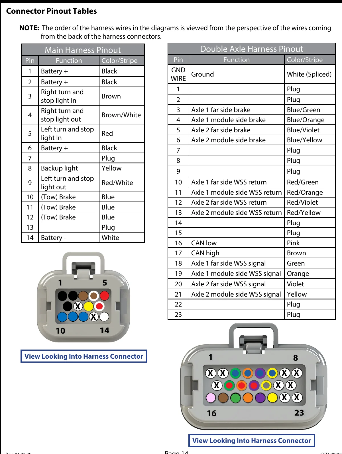
The connector-table note defines wire order from the perspective of wires entering the back of the harness connectors. Read that note along with the diagram and identify circuits by the table's pin, function, and color information.
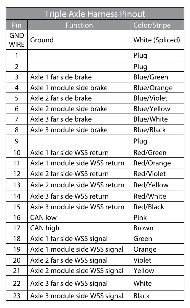
Select the table matching the axle arrangement. The tables distinguish module-side and far-side brakes, sensor signals, and sensor returns. The triple-axle table assigns circuits to positions that are plugged in the double-axle table, so the tables are not interchangeable.
How It Works
Harness architecture establishes circuit purpose
The main harness connects the controller to power, ground, and the tow vehicle connection; the axle harness connects the controller to the wheel ends and carries a factory diagnostic port. The manual calls brake magnets actuators, so recognizing that terminology helps prevent confusion between a brake-output circuit and a sensor circuit.
Ground routing affects the diagnostic path
The brake-magnet main ground connects all brake magnets to trailer chassis ground through either a frame grounding lug near the module or a wire routed forward to the trailer's main battery ground. Resistance in a shared ground path can affect multiple brake magnets, so tracing the actual ground arrangement is more useful than assuming the nearest chassis attachment is the correct test point.
Connector orientation and configuration must agree
The connector-table wire order is viewed from the perspective of wires entering the back of the harness connectors, not from an assumed mating-face view. Select the double-axle or triple-axle table, then match pin, function, color, axle, and module-side or far-side designation. The triple-axle table uses positions plugged in the double-axle table, making the tables noninterchangeable.
Step-by-Step Procedure
0/7 doneFigures
Diagnostic Chart
| Symptom | Check | Spec / Expected | Likely cause & fix |
|---|---|---|---|
| The suspected circuit cannot be confidently located in the harness. | Determine whether the circuit serves controller power, ground, or the tow vehicle connection, or instead runs toward the wheel ends; identify the factory diagnostic port separately. | The main harness serves power, ground, and the tow vehicle connection. The axle harness serves the wheel ends and carries the factory diagnostic port. | The technician may be searching the wrong harness branch or confusing the diagnostic port with a wheel-end connection. Basis: Lippert-Anti-Lock-Braking-System |
| An apparent missing terminal suggests an open circuit. | Confirm the trailer's axle arrangement and compare the connector with the matching table before treating an unused position as a defect. | Positions plugged in the double-axle table are assigned circuits in the triple-axle table. | Using the wrong axle table can make an intentionally plugged position appear to be a missing circuit. Basis: Lippert-Anti-Lock-Braking-System |
| The selected wire does not match the expected brake or sensor circuit. | Read the orientation note, view the connector from the wire-entry perspective, and cross-check pin, function, color, axle, and module-side or far-side designation. | Wire order is defined from the back of the harness connectors; tables distinguish brake circuits, sensor signals, and sensor returns. | A reversed viewing perspective or incorrect wheel-end designation can lead to testing an unrelated circuit. Basis: Lippert-Anti-Lock-Braking-System |
| Multiple brake magnets appear affected and the shared ground path is uncertain. | Trace the brake-magnet main ground to the frame lug near the module or to the wire routed forward to the trailer's main battery ground before selecting the fault-chart test point. | All brake magnets connect to trailer chassis ground through the documented brake-magnet main ground arrangement. | An incorrectly identified shared ground path can misdirect testing; a shared connection warrants inspection when multiple magnets are affected. Basis: Lippert-Anti-Lock-Braking-System |
At the Bay: Diagnose the Case
CASE 1 / 4
The suspected circuit cannot be confidently located in the harness.
- Test
- Compare
- Correct
Select the next check
Basis: Lippert-Anti-Lock-Braking-System. A likely cause is a hypothesis; confirm it with the applicable service procedure before repair.
Common Bay Mistakes
- ✕ Do not read wire-entry positions as though viewing the mating face.
- ✕ Do not identify a circuit by wire color alone.
- ✕ Do not substitute an axle table or confuse sensor return with brake-magnet ground.
- ✕ Support the trailer according to manufacturer recommendations before working underneath, and keep clear of moving parts.
Quick Check
Practice only — not scored.
Plan the Service Sequence
Planning practice only. Follow the applicable manufacturer's instructions, employer safety program and qualified supervision on real equipment.
Plan the first action. Compare the service steps with the bay mistakes.
Hands-on: Shop Test Equipment
ABS Sensor Gap & Blink-Code Scanner
Non-magnetic feeler gauge, AC millivolt meter on the sensor, ECU blink-code button
🛠 Equip your bay for this test →Symptom: Post-repair verification.
Spec limits used
- 1.00–1.75 mm — Wheel-speed sensor air gap (Lippert ABS manual, p.13)
- 068Ah / 0006h — Sensor fault codes (Lippert ABS)
- illustrative only — Sensor AC output while spinning (General shop practice)
Simulated readings for practice. Always follow the manufacturer's procedure and values on a real trailer.
Source: Lippert-Anti-Lock-Braking-System — 2-3, 14-15